12 english
5
Installation and connection (continued)
5.4 Electrical connection
The electrical connection is made via a plug connection
(for pin assignment see Tab. 5-2).
See the information about Cable routing on
page12.
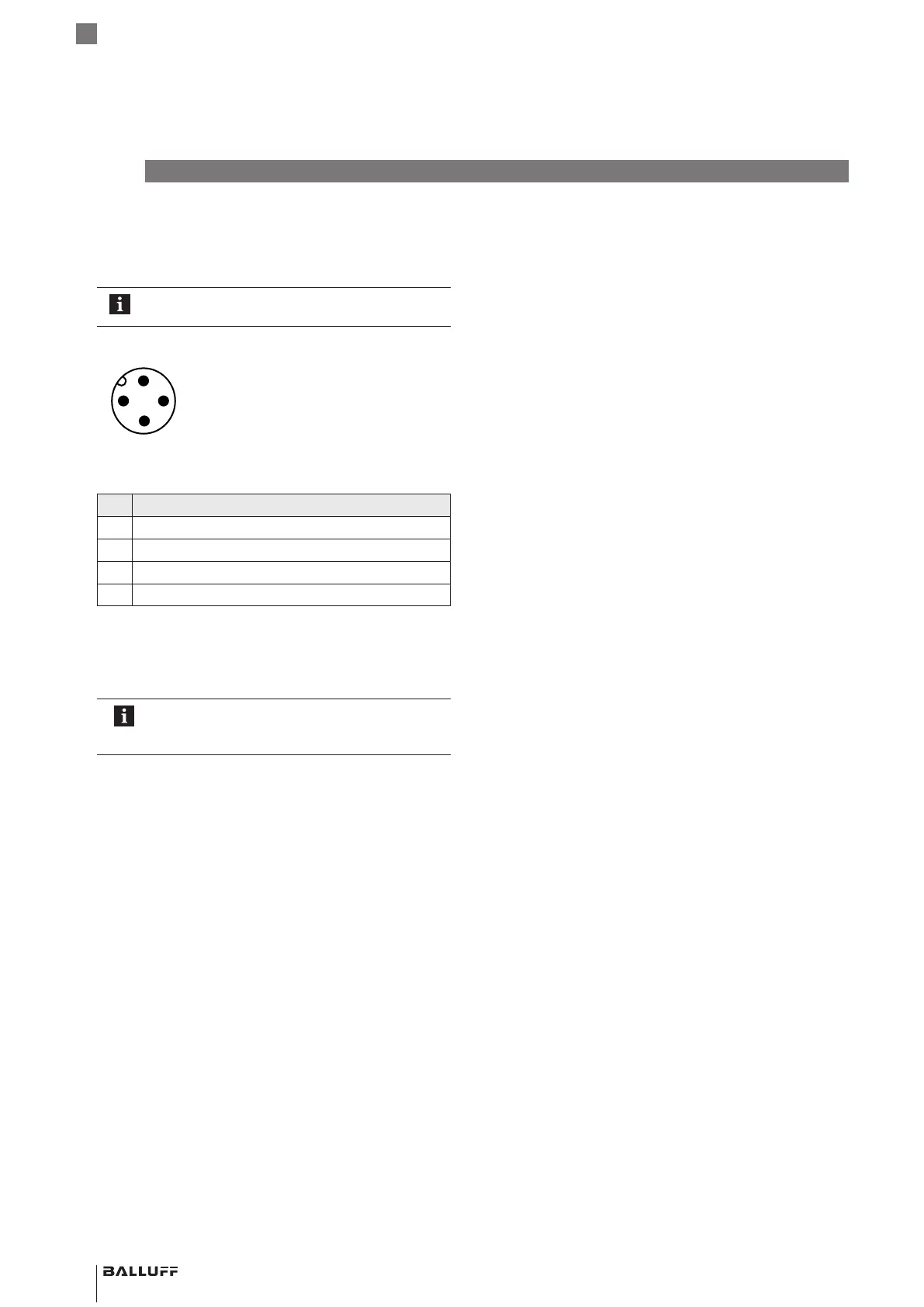
Fig. 5-9:
4
3
1
2
Pin assignment ofS04 (view from above on BTL)
Pin Signal
1 L+ (18…30V)
2 not assigned
1)
3 L− (GND)
4 C/Q (IO-Link communication)
1)
Non-assigned wires can be connected to GND on the control side.
Tab. 5-2: Pin assignmentS04
5.5 Cable routing
Defined ground!
The BTL and the control cabinet must be at the
same ground potential.
Magnetic fields
The position measuring system is a magnetostrictive
system. Ensure that there is sufficient distance between
the BTL and the transducer/holding cylinder and strong,
external magnetic fields.
Cable routing
All cables between BTL, control and power supply must
be routed tension-free. In order to avoid electromagnetic
interference, ensure sufficient distance to cables carrying a
heavy current and cables with high-frequency voltage
signals (e.g. of frequency converters).
Cable length
For IO-Link operation, the maximum cable length is 20m.
BTL PF _ 400- _ _ _ _ -C12NL _ _ -0-000S04
Magnetostrictive Linear Position Sensor – Profile Style
 Loading...


