www.balluff.com 11english
5
Installation and connection (continued)
5.3 Floating magnets
Observe the following when installing the magnet:
– To ensure the accuracy of the magnetostrictive linear
position sensor, fasten the magnet to the moving
member of the machine only using non-magnetizable
screws (stainless steel, brass, aluminum).
– The moving member must guide the magnet on a
parallel line to the BTL.
– Distance A between the magnet and parts made of
magnetizable material must be kept to at least 10 mm
(see Fig. 5-4 to Fig. 5-8).
– For distance B between the magnet and the BTL and
for the center offset C (see Fig. 5-4 to Fig. 5-8) the
following values must be maintained:
Magnet type Distance B
1)
Offset C
BTL5-P-3800-2 0.1…4mm ±2mm
BTL5-P-5500-2 5…15mm ±15mm
BTL5-P-4500-1 0.1…2mm ±2mm
BTL6-A-3800-2 4…8mm
2)
±5mm
BTL6-A-3801-2 4…8mm
2)
±5mm
1)
The selected distance must remain constant over the entire measuring
length.
2)
For optimal measurement results: 6…8mm
Tab. 5-1: Distance and offset for magnets (see Fig. 5-4 to Fig. 5-8)
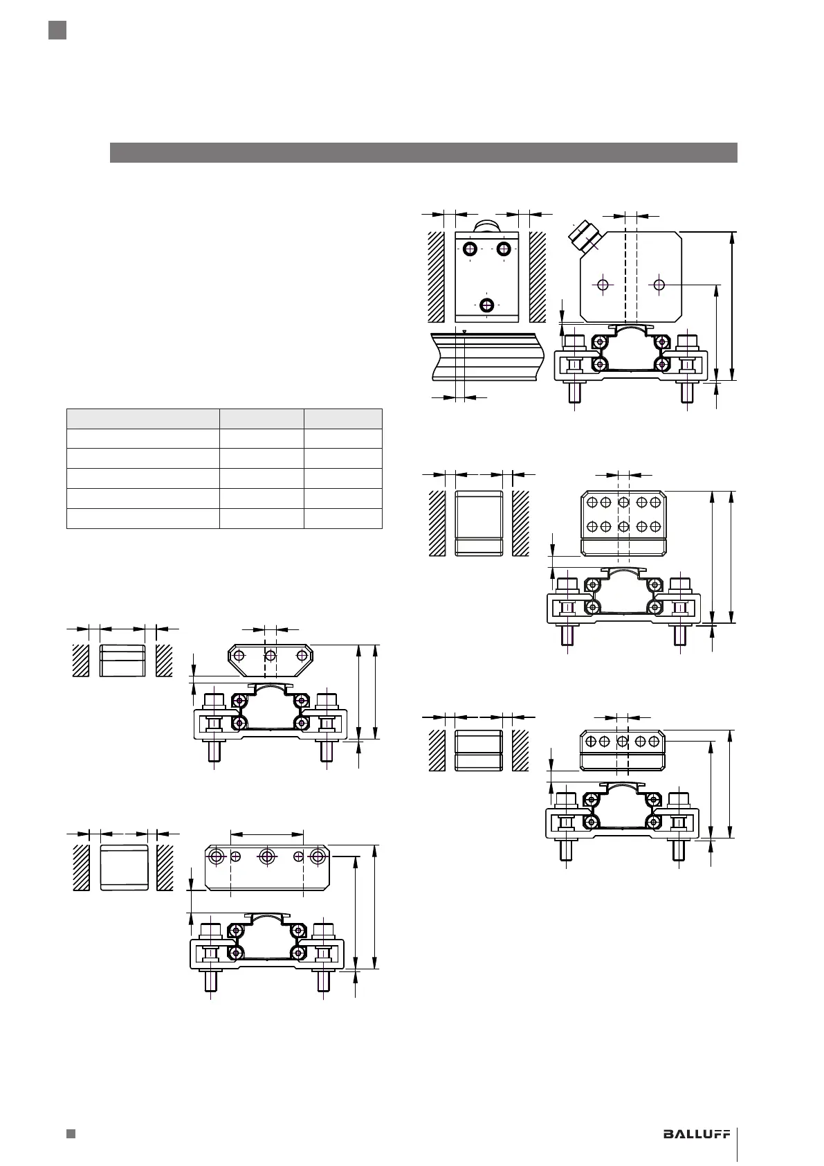
Fig. 5-4:
1
34+4
39+4
B
C
A A
Dimensions and spacing with magnet BTL5-P-3800-2
Fig. 5-5:
1
45+10
50+10
B
C
A A
Dimensions and spacing with magnet BTL5-P-5500-2
Fig. 5-6:
Plug with
LED
1
41.5+2
65+2
B
C
A A
4
Dimensions and spacing with magnet BTL5-P-4500-1
Fig. 5-7:
1
53+4
58+4
B
C
A A
Dimensions and spacing with magnet BTL6-A-3800-2
Fig. 5-8:
1
42+4
47+4
B
C
A A
Dimensions and spacing with magnet BTL6-A-3801-2
BTL PF _ 400- _ _ _ _ -C12NL _ _ -0-000S04
Magnetostrictive Linear Position Sensor – Profile Style
 Loading...


