www.balluff.com 11中文
5
安装和连接(接上页)
5.3 自由式位置指示器
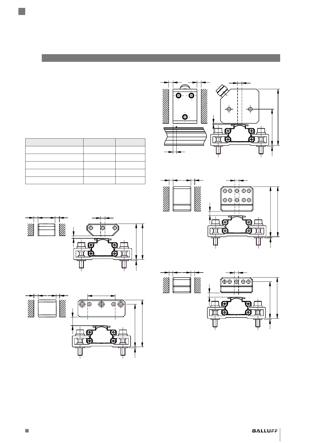
安装位置指示器时务必注意:
– 为确保磁致伸缩位移传感器的精度,使用非磁化螺栓
(不锈钢、黄铜、铝)将位置指示器固定到移动的机器
部件上。
– 移动的机器部件必须引导位置指示器沿着与BTL平行
的导轨前进。
– 位置指示器和磁化材料构成的部件之间的距离A至少应
为10mm(参见图5-4至图5-8)。
– 对于位置指示器和BTL之间的距离B以及中心偏置量C
(参见图5-4至图5-8)请遵守以下数值:
位置指示器的类型 距离B
1)
偏移量C
BTL5-P-3800-2 0.1…4mm ±2mm
BTL5-P-5500-2 5…15mm ±15mm
BTL5-P-4500-1 0.1…2mm ±2mm
BTL6-A-3800-2 4…8mm
2)
±5mm
BTL6-A-3801-2 4…8mm
2)
±5mm
1)
所选距离在整个测量长度上必须保持恒定。
2)
用于最佳测量结果:6…8mm
表5-1: 位置指示器距离和偏移(参见图5-4至图5-8)
图5-4:
1
34+4
39+4
B
C
A A
使用位置指示器BTL5-P-3800-2的尺寸和距离
图5-5:
1
45+10
50+10
B
C
A A
使用位置指示器BTL5-P-5500-2的尺寸和距离
图5-6:
带LED
的插头
1
41.5+2
65+2
B
C
A A
4
使用位置指示器BTL5-P-4500-1的尺寸和距离
图5-7:
1
53+4
58+4
B
C
A A
尺寸和距离用位置指示器BTL6-A-3800-2
图5-8:
1
42+4
47+4
B
C
A A
尺寸和距离用位置指示器BTL6-A-3801-2
BTL PF _ 400- _ _ _ _ -C12NL _ _ -0-000S04
磁致伸缩位移传感器–型材结构
 Loading...


