www.balluff.com 7english
13.5
Ø D1
G
12.8
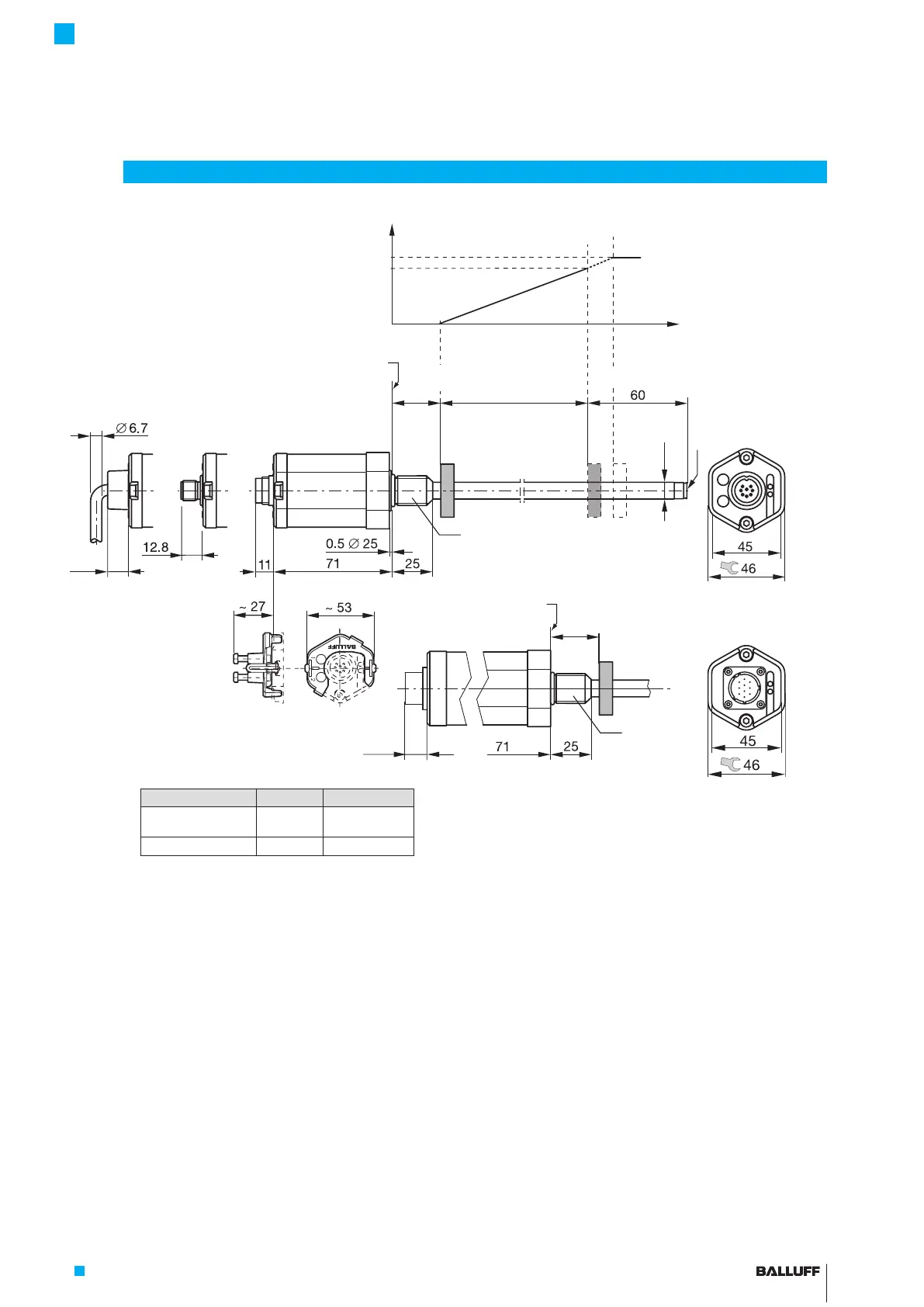
Magnet: Defines the position to be measured on the
waveguide. Magnets are available in various models and
must be ordered separately (see accessories on
page25).
Nominal length: Defines the available measuring range.
Rods with various nominal lengths from 25 mm to
7620mm are available depending on the version:
– Ø10.2mm: Nominal length from 25mm to 7620mm
– Ø8mm: Nominal length from 25mm to 1016mm
Damping zone: Area at the end of the rod that cannot be
used for measurements, but which may be passed over.
Calibration device: Additional device for calibrating the
transducer (not for BTL7-….-S140).
3
Construction and function
Fig. 3-1: BTL7...A/B/Y/Z(8)... transducer, construction and function
3.1 Construction
Electrical connection: The electrical connection is made
via a cable or a connector (see Ordering code on
page29).
BTL housing: Aluminum housing containing the
processing electronics.
Mounting thread: We recommend assembling this
transducer on the mounting thread:
– BTL7-…-A/B: M18×1.5
– BTL7-…-Y/Z: 3/4"-16UNF
The transducers with Ø10.2mm have an additional thread
at the end of the rod to support larger nominal lengths.
Version D1 G
...-A/B/Y/Z-... 10.2 mm Thread
M4x4/6deep
...-A8/B8/Y8/Z8-... 8 mm No thread
Calibration device
BTL7-...-Cable
BTL7-...-S140
BTL7-...-S115 BTL7-...-S32/S135
Mounting surface
Thread size:
A: M18x1.5
Y: 3/4"-16UNF
A: 30-1 mm
Y: 2"-0.04"
1)
Unusable area
2)
Not included in scope of delivery
3)
Not included in scope of delivery of
BTL7-...-S140
Thread size:
B: M18x1.5
Z: 3/4"-16UNF
2)
3)
1)
Mounting surface
1)
Nominal length =
Measuring range
Null point End point
Output signal with rising
characteristic:
Error signal
100 %
0 %
B: 30-1 mm
Z: 2"-0.04"
Damping zone
1)
Magnet
2)
Top view of the
BTL7-...-S32
Top view of the
BTL7-...-S140
BTL7-A/C/E/G_ _ _-M_ _ _ _-A/B/Y/Z(8)-S32/S115/S135/S140/KA_ _/FA_ _
Micropulse Transducer - Rod Style
 Loading...


