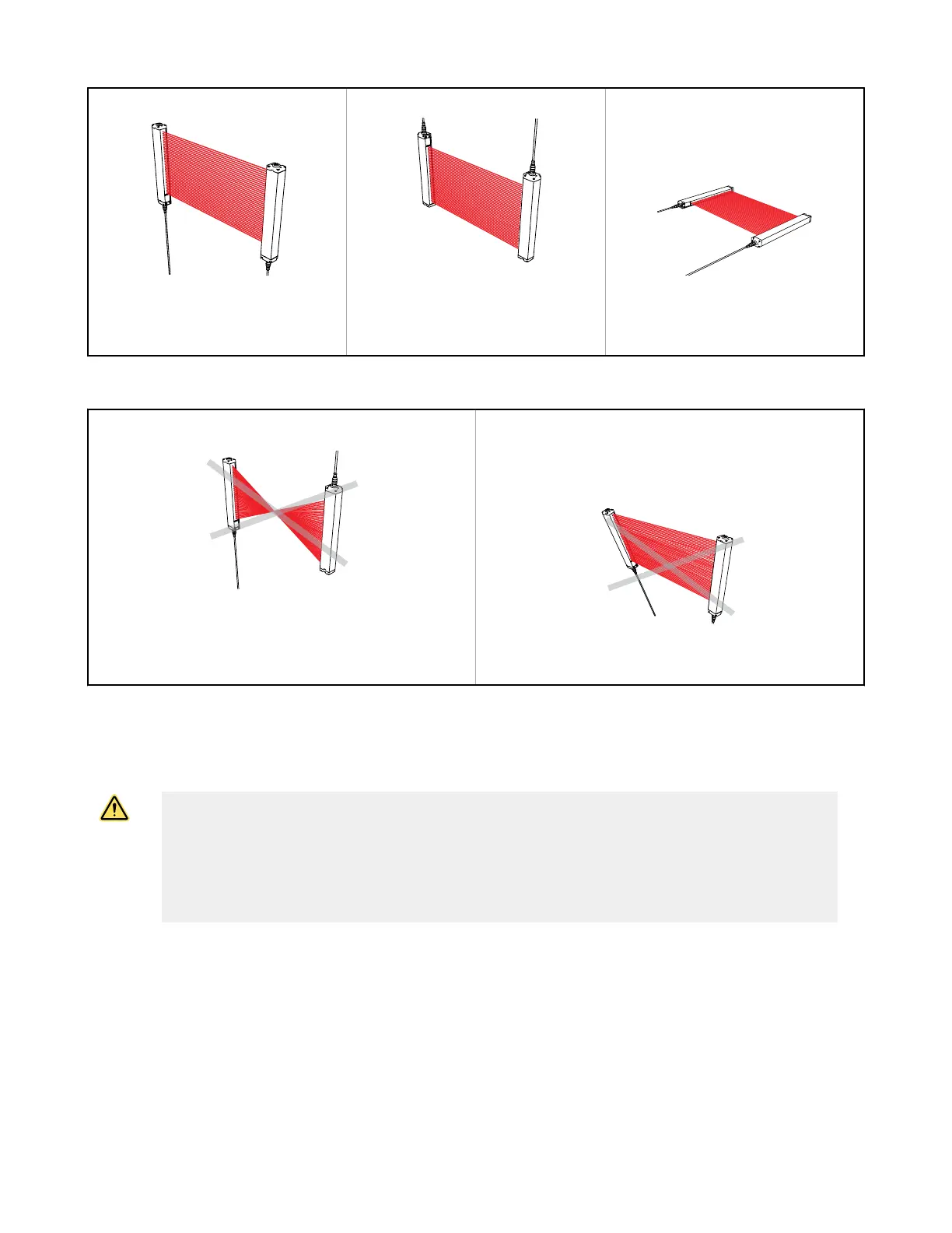
Both cable ends down Both cable ends up Orientation parallel to floor with both
cable ends pointing in the same
direction
Figure 5. Examples of Correct Emitter/Receiver Orientation
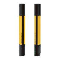
Cable ends point in opposite directions
Problem: Voids in defined area
Emitter and receiver not parallel to each other
Problem: Reduced excess gain
Figure 6. Examples of Incorrect Emitter/Receiver Orientation
5.2.6 Adjacent Reflective Surfaces
WARNING:
• Do not install the system near reflective surfaces
• Reflective surfaces could reflect the sensing beam(s) around an object or person within the
defined area, preventing detection by the system. Failure to prevent reflection problems results in
incomplete guarding and an optical short circuit that could result in serious injury or death.
• Do not locate the defined area near a reflective surface. Perform the trip test, as described in the
product documentation, to detect such
reflection(s).
A reflective surface located adjacent to the defined area may deflect one or more beams around an object in the defined
area. In the worst case, an optical short circuit may occur, allowing an object to pass undetected through the defined area.
This reflective surface may result from shiny surfaces or glossy paint on the machine, the workpiece, the work surface, the
floor, or the walls. Beams deflected by reflective surfaces are discovered by performing the trip test and the periodic
checkout procedures. To eliminate problem reflections:
• If possible, relocate the sensors to move the beams away from the reflective surface(s), being careful to maintain
adequate separation distance
• Otherwise, if possible, paint, mask, or roughen the shiny surface to reduce its reflectivity
• Where these are not possible (as with a shiny workpiece or machine frame), determine the worst-case resolution
resulting from the optical short circuit and use the corresponding depth penetration factor (Dpf or C) in the Safety
Distance (Minimum Distance) formula; or mount the sensors in such a way that the receiver's field of view and/or the
emitter's spread of light are restricted from the
reflective surface
EZ-SCREEN
®
14/30 mm Safety Light Screen
www.bannerengineering.com - Tel: + 1 888 373 6767 25