There are no compatibility issues retrofitting receivers with aux output into earlier installations, if precautions are taken to
prevent EDM2 (pin 2, orange/black wire) from shorting to ground or another source of energy.
5.11 Remote Test Input
The 5-pin EZ-SCREEN emitter models (model numbers SLSE..-..Q5) provide a Test function. A pair of wires is connected
from the emitter to an external switch, typically a normally open contact, held closed. Opening the switch “turns off” the
emitter, simulating an interruption of one or more light beams; all OSSD outputs will turn OFF.
This remote test input function may be useful for EZ-SCREEN setup and to verify machine control circuit operation.
See
Specifications
on page 84,
Electrical Connections to the Guarded Machine
on page 38, and
Sensor "Swapability"
on
page 42 for more information.
5.12 Preparing for System Operation
After the initial trip test has been accomplished, and the OSSD safety outputs and EDM connections have been made to the
machine to be controlled, the EZ-SCREEN is ready for testing in combination with the guarded machine.
The operation of the EZ-SCREEN with the guarded machine must be verified before the combined System and machine
may be put into service. To do this, a Qualified Person must perform the Commissioning Checkout Procedure.
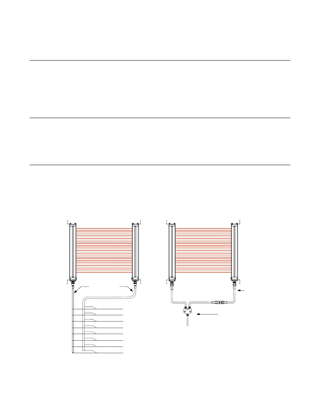
5.13 Sensor "Swapability"
This wiring option provides sensor interchangeability (or “swapability”)—the ability to install either sensor at either QD
connection.
To wire the emitter, use only three conductors (Brown = +24 V dc, Blue = 0 V dc, and Green/Yellow = GND). Connect the
remaining wires in a parallel connection (color-for-color) to the receiver cable.
The resulting installation provides the ability to swap the emitter and receiver position. This wiring option provides
advantages during installation, wiring, and troubleshooting.
Bn
Or/Bk
Or
Wh
Bk
Bu
Gn/Ye
Vi
+24V dc
QDE-8..D Cables
EDM2
EDM1
OSSD2
OSSD1
0V dc
Ground
Reset
Emitter
Receiver
Individual 8-Wire Cordsets 8-Wire Splitter Cordsets
Emitter
Receiver
CSB.. Splitter Cordset
DEE2R..
Figure 17. 8-pin connectors (optional hookup)
Model CSB.. splitter cordsets and DEE2R.. double-ended cables allow easy interconnection between an EZ-SCREEN
receiver and emitter, providing a single trunk cable for the optional "swapable" wiring (see
Routing Cordsets
on page 30).
EZ-SCREEN
®
14/30 mm Safety Light Screen
42 www.bannerengineering.com - Tel: + 1 888 373 6767