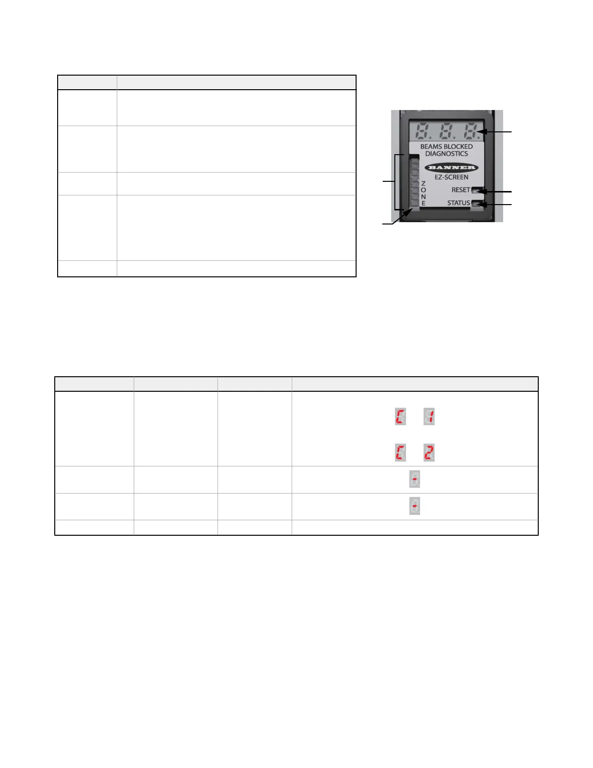
Receiver:
Key Description
A
Reset indicator (Yellow)—shows System status:
• Run mode (ON)
• Waiting for a reset (flashing)
B
Status indicator (Red/Green)—shows System status:
• Reduced Resolution enabled (flashing green)
• Outputs are ON or OFF (green ON or red ON)
• The System is in Lockout condition (flashing red)
C
3-Digit Diagnostic Display—indicates specific error, configuration
conditions, or total number of blocked beams.
D
Zone indicators (Red/Green)—each shows status of approximately 1/8 of
the total beams:
• Aligned and clear (green ON)
• Blocked and/or misaligned (red ON)
• Fixed blanked area
(flashing green)
E
Zone 1 Indicator—indicates beam synchronization status
Figure 26. Receiver
6.4.1 Emitter
A single bi-color red/green Status indicator shows whether power is applied, and whether the emitter is in Run mode,
optional Test mode, or Lockout status. A Diagnostic Display indicates a
specific error code when the emitter is in Lockout;
the display also momentarily indicates the scan code setting at power-up or when changed.
Operating Status Required Event Status Indicator Diagnostic Display
Power-up Apply Power Red single-flash
Scan code flash 3 times, alternates
then
or
then
Run Mode Passes internal tests Green
Test Mode Open Test switch Flashing green
Lockout Internal/external fault Flashing red Displays error code (see
Troubleshooting
on page 77)
6.4.2 Receiver
Bi-color Red/Green Zone indicators show whether a section of the
defined area is aligned and clear, or is blocked and/or
misaligned. A Yellow Reset indicator shows when the System is in Run mode or is waiting for a reset. There are 8 Zone
indicators for all model lengths, each of which indicates Blocked/Clear conditions for approximately 1/8 of the total light
screen.
A bi-color Red/Green Status indicator shows when the OSSD outputs are ON (Green) or OFF (Red), or the System is in
Lockout status
(flashing Red). The Diagnostic Display indicates the receiver’s trip (–) or latch (L) configuration setting and
displays a
specific error code when the receiver is in Lockout. The Diagnostic Display also momentarily indicates the scan
code at power-up or when changed.
EZ-SCREEN
®
14/30 mm Safety Light Screen
52 www.bannerengineering.com - Tel: + 1 888 373 6767