5.4 Sensor Mounting and Mechanical Alignment
Verify that:
• The emitter and receiver are directly opposite
each other
• Nothing is interrupting the
defined area
• The defined area is the same distance from a
common reference plane for each sensor
• The emitter and receiver are in the same plane
and are level/plumb and square to each other
(vertical, horizontal, or inclined at the same
angle, and not tilted front-to-back or side-to-
side)
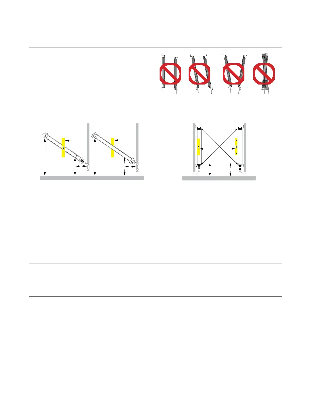
Figure 11. Incorrect Sensor Alignment
Level Surface
X X
Emitter Receiver
level
level
Y Y
Z
Z
Level Surface
A B
level level
XX
Angled or Horizontal Installations – verify that:
• Distance X at the emitter and receiver are equal
• Distance Y at the emitter and receiver are equal
• Distance Z at the emitter and receiver are equal from
parallel surfaces
• Vertical face (the window) is level/plumb
• Defined area is square. Check diagonal
measurements if possible; see Vertical Installations,
on the right.
Vertical Installations – verify that:
• Distance X at the emitter and receiver are equal
• Both sensors are level/plumb (check both the side
and face)
• Defined area is square. Check diagonal
measurements if possible (Diagonal A = Diagonal B).
5.5 Mounting the Reset Switch
Mount the reset switch in a location that complies with the warning in
Reset Switch Location
on page 23. See
Initial
Electrical Connections
on page 31 for electrical connection.
5.6 Routing Cordsets
Attach the required cordsets to the sensors, and route the sensor cables to the junction box, electrical panel, or other
enclosure in which the interface module, the redundant mechanically linked interposing relays, FSDs, or other safety-related
parts of the control system are located. This must be done per local wiring code for low-voltage dc control cables and may
require installation of electrical conduit. See
Accessories
on page 88 for selection of Banner supplied cables.
EZ-SCREEN is designed and manufactured to be highly resistant to electrical noise and to operate reliably in industrial
settings. However, extreme electrical noise may cause a random Trip or Latch condition; in extreme cases, a Lockout is
possible.
Emitter and receiver wiring is low voltage; routing the sensor wires alongside power wires, motor/servo wires, or other high
voltage wiring may inject noise into the EZ-SCREEN System. It is good wiring practice, and sometimes may be required by
code, to isolate emitter and receiver cables from high-voltage wires, avoid routing cables close to “noisy” wiring, and
provide a good connection to earth ground.
Sensor cabling and any interconnect wiring should have an insulation temperature rating of at least 90 °C (194 °F). In
addition, QD cabling and any interconnect wires should meet the
specifications in the following table:
EZ-SCREEN
®
14/30 mm Safety Light Screen
30 www.bannerengineering.com - Tel: + 1 888 373 6767