11 Specifications
11.1 General Specifications
Short Circuit Protection
All inputs and outputs are protected from short circuits to +24 V dc or
dc common
Electrical Safety Class
III (per IEC 61140: 1997)
Safety Rating
Type 4 per IEC 61496-1, -2
Category 4 PL e per EN ISO13849-1
SIL3 per IEC 61508; SIL CL3 per IEC 62061
PFHd: 4.3 × 10
-9
Operating Range
14 mm models: 0.1 m to 6 m (4 in. to 20 ft)
30 mm models: 0.1 m to 18 m (4 in. to 60 ft)
— Range decreases with use of mirrors and/or lens shields:
• Lens shields — approx 10% less range per shield
• Glass-surface mirrors — approx 8% less range per mirror
See the
specific mirror datasheet for more information.
Resolution
14 mm or 30 mm, depending on model
Effective Aperture Angle (EAA)
Meets Type 4 requirements per IEC 61496-2
±2.5° at 3 m
Operating Conditions
0 °C to +55 °C (+32 °F to +131 °F)
95% maximum relative humidity (non-condensing)
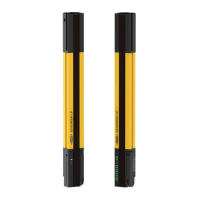
Enclosure
Extruded aluminum housing with yellow polyester powder finish
standard (optional black or white or nickel-plated silver finish) and well-
sealed, rugged die-cast zinc end caps, acrylic lens cover, copolyester
access cover. End caps on silver models are also nickel-plated. ESD-
safe models have static-dissipative acrylic lens cover.
Environmental Rating
IEC IP65
Shock and Vibration
Components have passed vibration and shock tests according to IEC
61496-1. This includes vibration (10 cycles) of 10-55 Hz at 0.35 mm
(0.014 in) single amplitude (0.70 mm peak-to-peak) and shock of 10 g
for 16 milliseconds (6,000 cycles).
Mounting Hardware
Emitter and receiver each are supplied with a pair of swivel end-
mounting brackets. Models 1050 mm and longer also include a swivel
center-mount bracket. Mounting brackets are 8-gauge cold-rolled steel,
black zinc
finish.
Cables and Connections
See
Accessories
on page 88
Certifications
11.2 Emitter Specifications
Supply Voltage at the Device
24 V dc ±15% (use a SELV-rated power supply according to EN IEC
60950). The external voltage supply must be capable of buffering brief
mains interruptions of 20 ms, as specified in IEC/EN 60204-1.
Residual Ripple
± 10% maximum
Supply Current
100 mA maximum
Status Indicators
One bi-color (Red/Green) Status Indicator: indicates operating mode,
lockout or power Off condition
7-Segment Diagnostic indicator (1 digit): indicates proper operation,
scan code, or error code
Wavelength of Emitter Elements
Infrared LEDs, 850 nm at peak emission
Remote Test Input Optional—available only on model SLSE..-..Q5 emitters
Test mode is activated either by applying a low signal (less than 3 V dc)
to emitter TEST#1 terminal for a minimum of 50 milliseconds, or by
opening a switch connected between TEST#1 and TEST#2 and +24 V
dc for a minimum of 50 milliseconds. Beam scanning stops to simulate
a blocked condition. A high signal at TEST#1 deactivates Test mode.
High Signal: 10 to 30 V dc
Low Signal: 0 to 3 V dc
Input Current: 35 mA inrush, 10 mA maximum
Controls and Adjustments
Scan Code Selection: 2-position switch (code 1 or 2). Factory default
position is code 1.
EZ-SCREEN
®
14/30 mm Safety Light Screen
84 www.bannerengineering.com - Tel: + 1 888 373 6767