5.3 Mounting the Emitter and Receiver
Emitter/receiver pairs with 14 mm (0.55 in) resolution may be spaced from 0.1 m to 6 m (4 in to 20 ft) apart. Emitter/receiver
pairs with 30 mm (1.18 in) resolution may be spaced from 0.1 m to 18 m (4 in to 60 ft) apart. The maximum distance
between an emitter and its receiver is reduced if corner mirrors are used (see
Use of Corner Mirrors
on page 26). The
supplied brackets allow ±30° rotation, when mounted to the sensor end caps.
From a common point of reference, ensuring the Safety Distance (Minimum Distance) calculated in
Calculating the Safety
Distance (Minimum Distance)
on page 19, make measurements to locate the emitter and receiver in the same plane, with
their midpoints and display ends directly opposite each other.
Note: The connector ends of both sensors must point in the same direction (see
Emitter and Receiver
Orientation
on page 24).
Mount the emitter and receiver mounting brackets using the supplied M6 bolts and Keps nuts, or user-supplied hardware.
Mount the emitter and receiver in their brackets; position their windows directly facing each other. Measure from a reference
plane (for example, a level building floor) to the same point(s) on the emitter and receiver to verify their mechanical
alignment. Use a carpenter’s level, a plumb bob, or the optional LAT-1 Laser Alignment Tool (see
Accessories
on page
88), or check the diagonal distances between the sensors to achieve mechanical alignment. Final alignment procedures
are explained in
Initial Checkout Procedure
on page 32.
Center mounting brackets must be used with longer sensors if they are subject to shock or vibration. In such situations, the
sensors are designed to be mounted with up to 900 mm (35.43 in) unsupported distance (between brackets). Sensors 1050
mm (45.33 in) and longer are supplied with a center bracket to be used as needed with the standard end-cap brackets.
1. Attach the center bracket to the mounting surface when mounting the end-cap brackets.
2. Attach the clamp to both slots of the housing, using the included M5 screws and T-nuts.
3. After the sensor is mounted to the end-cap brackets, attach the clamp to the center bracket using the supplied M5
screw.
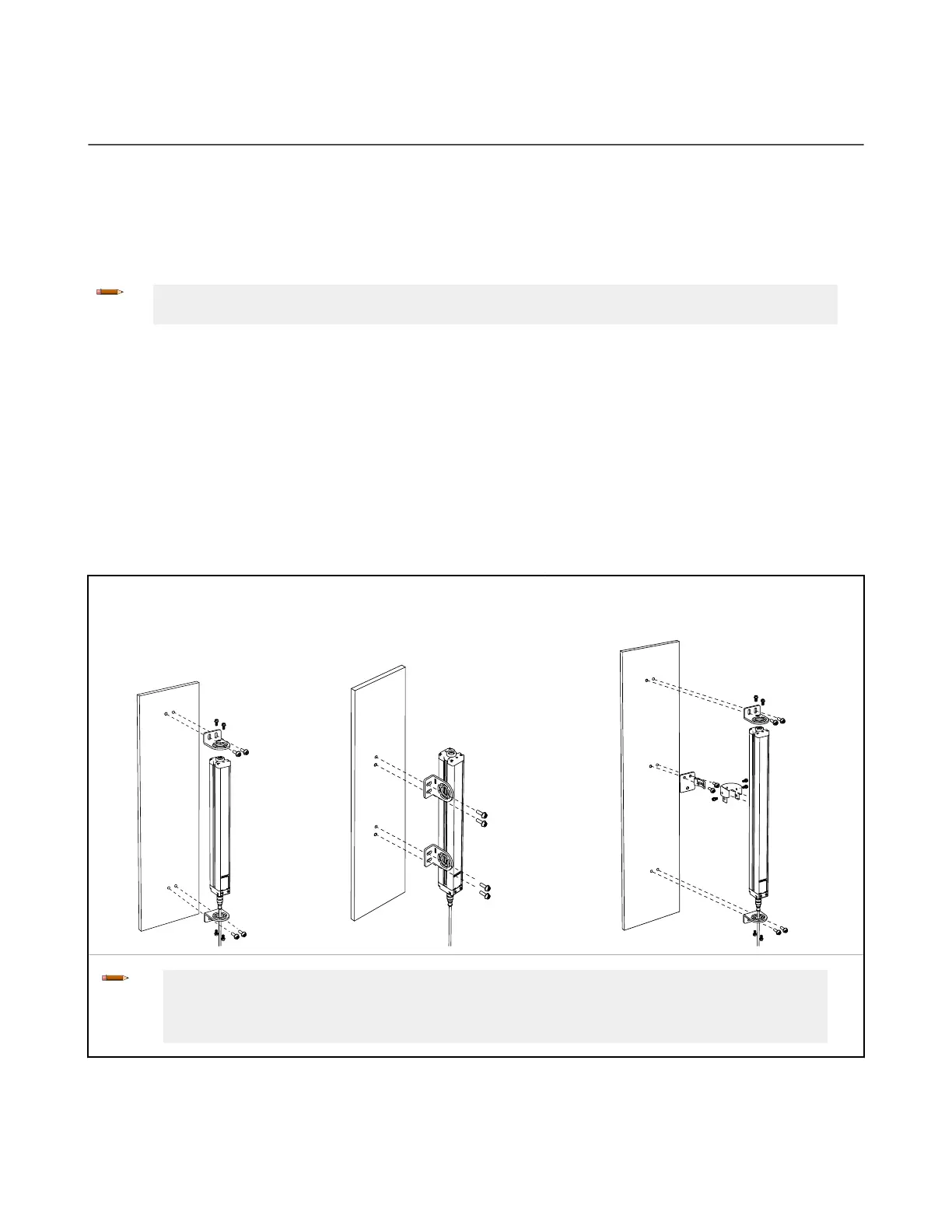
End-Cap Brackets
(supplied with each emitter and receiver) Swivel Center Bracket (supplied with emitters
and receivers 1050 mm and longer)
End-Mounted
Side-Mounted (two sensor brackets
may be substituted)
Note:
• EZ-SCREEN sensor brackets are designed to mount directly to MSA Series stands, using the
hardware supplied with the stands (see
Appropriate Applications and Limitations
on page 9)
• See
Specifications
on page 84 for mounting bracket dimensions
Figure 10. Sensor Brackets
EZ-SCREEN
®
14/30 mm Safety Light Screen
www.bannerengineering.com - Tel: + 1 888 373 6767 29