P/N 133487 99
Banner Engineering Corp. • Minneapolis, U.S.A.
www.bannerengineering.com • Tel: 763.544.3164
SC22-3 Safety Controller
Instruction Manual
Appendix A
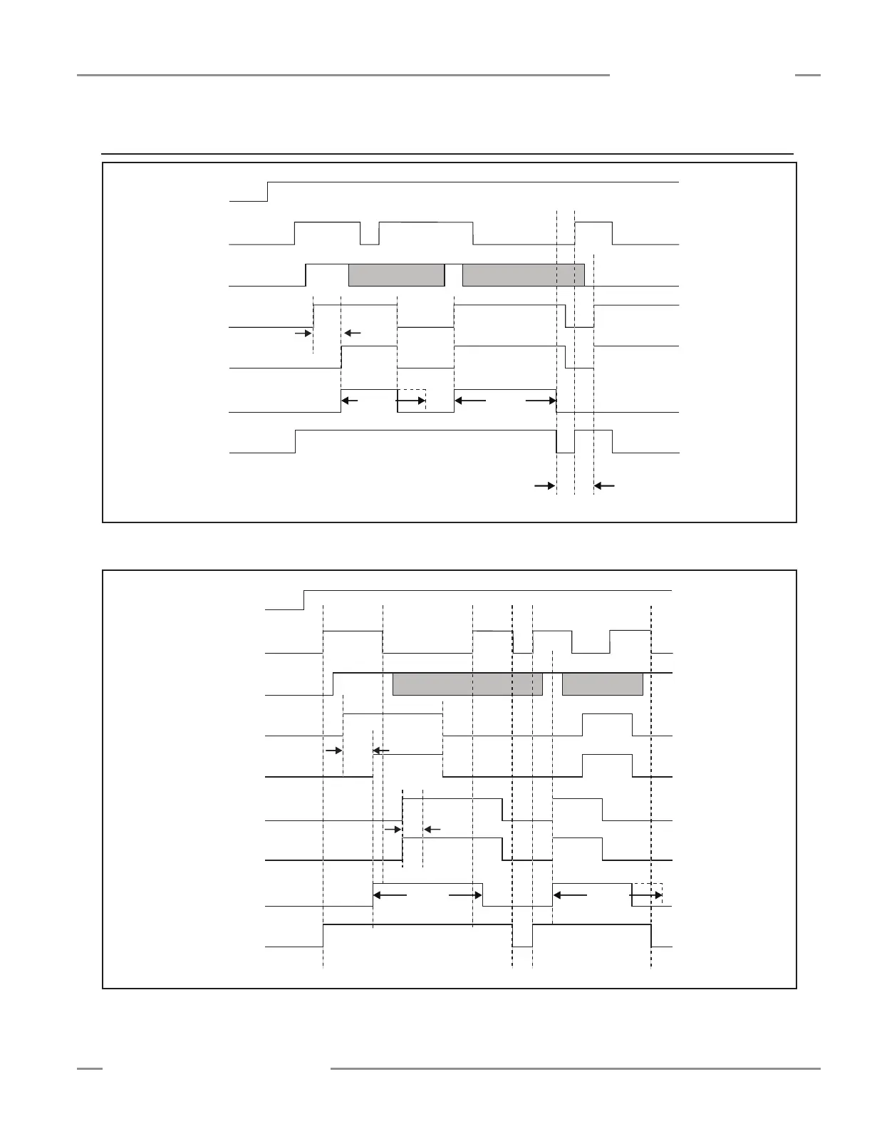
A.11.9 Mute Timing Sequences
Power
Safety Light Screen
Mute Enable
Mute Sensor 1
Mute Sensor 2
Backdoor Timer
Safety Output
Max.
Time
Max.
Time
Max.
Time
Max.
Time
< 3s< 3s
Mute cycle ends due to the expiration
of the Backdoor Timer
Mute cycle ends due to the expiration
of the Backdoor Timer
Mute cycle prevented due to
open Mute Enable input
Mute cycle prevented due to
open Mute Enable input
Power
Safety Light Screen
Mute Enable
Mute Sensor 1
Mute Sensor 2
Mute Sensor 3
Mute Sensor 4
Backdoor Timer
Safety Output
Max.
Time
Max.
Time
Max.
Time
Max.
Time
< 3s< 3s
< 3s< 3s
Figure A-9. Mute timing diagram with two mute sensors, mute enable, safety light screen and limited mute time. Mutable safety
device configured for Auto Reset.
Figure A-10. Mute timing diagram with four mute sensors, mute enable, safety light screen and limited mute time. Safety light
screen configured for Auto Reset.