102 P/N 133487
Banner Engineering Corp. • Minneapolis, U.S.A.
www.bannerengineering.com • Tel: 763.544.3164
SC22-3 Safety Controller
Instruction Manual
Appendix B
B.3 Interface Elements: Tool Bar, I/O Property Files and
Documents
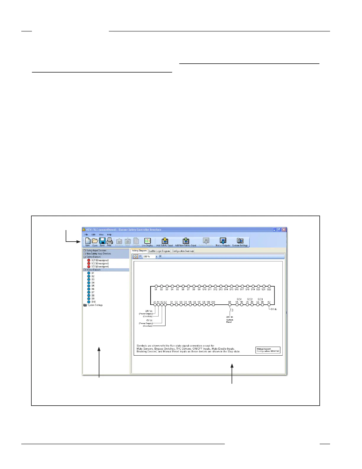
The Main screen will appear on the computer when the
application launches. You will be using the functions in each
section of the window during this tutorial.
I/O Properties
Double-click to access
property settings.
Tool Bar
Documents
Section
B.4 Documents
The Wiring Diagram shown in the screen shows its numbered
terminals:
S1 through S22 for input devices (both safety and non-safety)
A1 for +24V dc and A2 for 0V dc
O1 through O10 for Controller and I/O status indication
SO1 (1A and 1B), SO2 (2A and 2B) and SO3 (3A and 3B) for
connections to the Safety Outputs
SR, the Controller’s system reset terminal (shown with a push
button symbol)
• Click on the Ladder Logic Diagram tab just above the Wiring
Diagram. No logic circuit elements are in place yet.
• Click on the Configuration Summary tab just next to the
Ladder Logic Diagram tab. Only some default system settings
are visible.
The diagrams and the configuration summary will take form as
the configuration develops.
Figure B-1. PCI main screen, ready for configuration