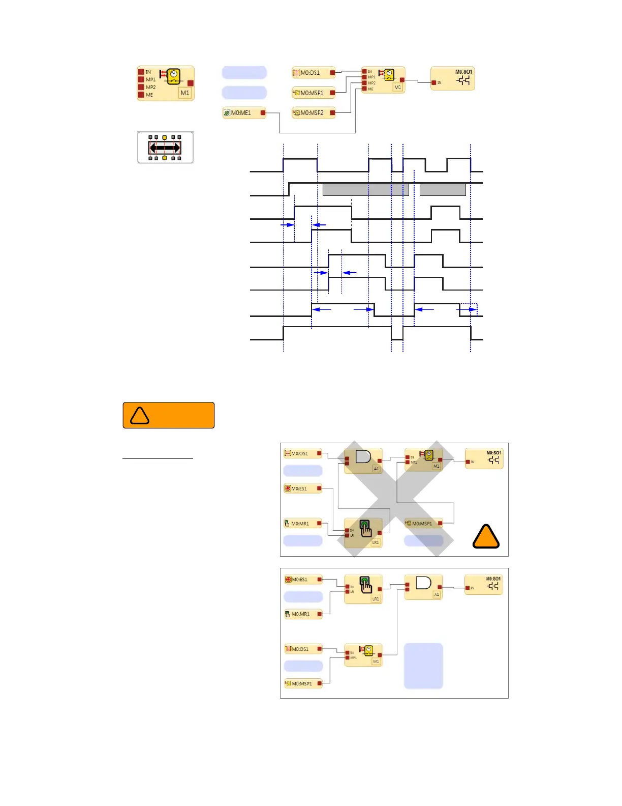
Figure 31. Timing Diagram—Two-Way Muting Block, Two Muting Sensor Pairs
Improper E-Stop Control
NOT RECOMMENDED
The configuration top right shows OS1 and E-Stop
button ES1 with a Latch Reset LR1 connected to
a mute function via the AND function. In this case
both ES1 and OS1 will be muted.
If there is an active mute cycle in progress and the
E-Stop button is pressed (switched to the Stop
state), SO1 will not turn Off. This will result in a
loss of safety control and may lead to a potential
hazardous condition.
Proper E-Stop Control
The configuration to the right shows OS1
connected directly to the Mute block M1. M1 and
ES1 are both inputs to AND A1. In this case both
M1 and ES1 control SO1.
If there is a an active mute cycle in progress and
the E-Stop button is pressed (switched to the Stop
state), SO1 will turn Off.
E-Stop Button control authority when using the Mute function
Warning
!
!
Figure 32. Emergency Stop and Mute Function
E-stop buttons, rope pulls, enabling devices, external device monitoring, and bypass switches are non-mutable devices or
functions.