3. Lenses & Lens selection
Image 3-2
2. Take the lens ass embly out of its packing m aterial and rem ove the lens caps on both sides.
Caution: Do not touch the glass of the lens!
3. Ensure that the Lens Holder stands in the On-Axis position (horizontal and vertical m id position). As best as possible.
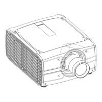
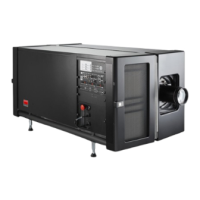
4. Place the Lens Holder in the “locked” position by moving the lens loc k handle (reference 1 image 3-3) to the left, away from the
lens power supply socket (reference 2 image 3-3 ).
5. Gently inse rt the lens in s uch a way that the lens connector matches the s ocket. To prevent collision o f the lens ensure you centre
the lens and keep it on-axis while approaching.
Warning: Do not release the Lens yet, as the Lens may fall out of the Lens Holder.
6. Push the lens completely agains t the Lens Holder front plate. An audible click should be noticed. O nc e seated, there m ay be
no airgap between lens flange and Lens Holder front plate.
Caution: Ensure that the lock handle remains in th e “locked” pos ition.
1
2
C
l
i
c
k
Image 3-3
Note: For frequent installation and removal of the lens it is recommended to install the lens while the lock handle is in “open”
position (to the right) a nd put the lock han
dle in “locked” position once the lens is inserted. Then check if the lens is
properly installed by t rying to pull the lens out of the Lens H older. (this alternative procedure r esult in less wear of the
Lens Holder)
7. Check if the lens is really secured by trying to pull the lens out of the Le ns Holder.
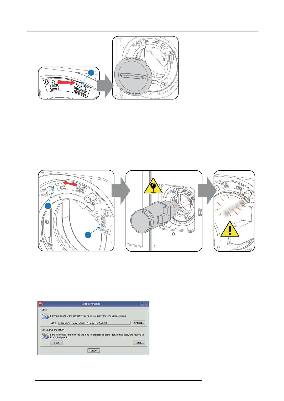
8. Activate the corresponding lens parameters for the installed lens. (See user guide of the Com municator chapter Inst allation >
Advanced > Lens parameters)
Caution: Not using the correct lens parameters could result in lens damage.
Image 3-4
18 R5906787 THOR 26/01/2018
 Loading...