4. Input & Communication
10
Key b utton
The (security) Key button (reference 10 image 4-4) is used for the authorization procedure to clear tamper errors etc. Pin
codes can be added/changed with the Com mu nicator. The bac klight of the Key button is normally green. If the DCI security
is tampered then the backlight of the Ke y button is red.
11
Zoom button
The Zoom button (reference 11 image 4-4) allows you to zo om in or out the projected im age on the s creen. The backlight of
the Zoom button is red in case the end of range is reached.
In c ase no lens (file) is selected the Zoom button remains inactive. No b acklight.
12
Media control buttons
Buttons (reference 12 image 4-4) allowing you to navigate through the content on the integrated media server. (this feature
is not yet implem ented in the software, future expansion).
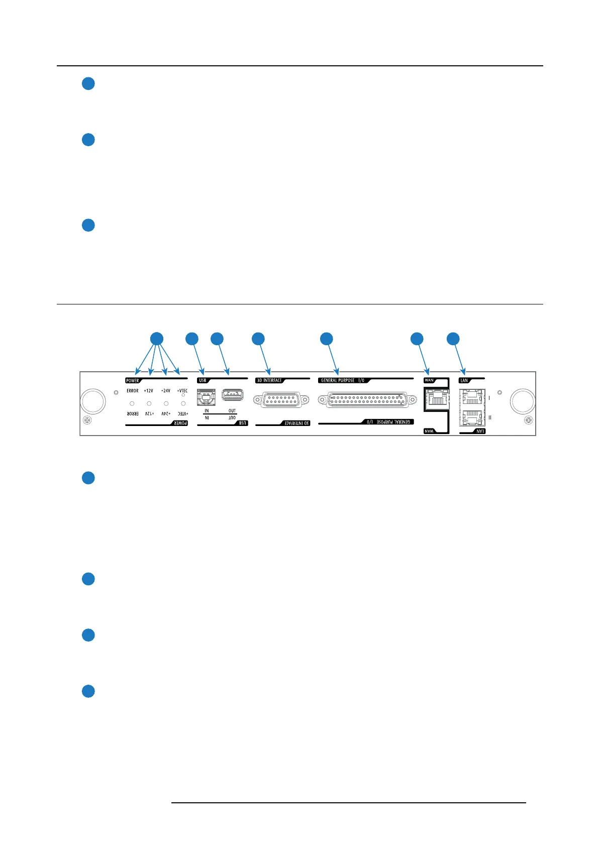
4.5 Cinema Controller
Location of the communication ports
5 6 74321
Image 4-5
Functionality
1
Diagnostic LEDs
The f ront plate of the Cinema Controller contains 4 diagnostic LEDs to display the status of the power supply (reference 1
image 4-5):
• +VTEC supply.
• +24V supply.
• +12V supply.
• general power supply (ERROR).
2
USB IN port
The Cinema Controller is equipped with a USB port, type “B” connector, (reference 2 image 4-5) to c onnect upstream devices
(E.g. PC). This USB port is used to c omm unicate with the
projector via RS232 comm ands (Virtual comport). The USB IN
port remains ope rational in S tandby mode.
3
USB OUT port
The Cinem a Controller is equipped with a USB po
rt, type “A” co nnector, (reference 3 im age 4-5) which can be us ed to power
handheld d evices within U SB spec (MAX 500mA/5V]. No other functionality supported (Future expansion). The USB OUT
port remains ope rational in S tandby mode.
4
3D INTERFACE
3D interface port (reference 4 image 4-5. Can be us ed to connect external 3D devices to the projector. All signals necessary
for 3D pro jection can be provided via this c onnector. The 3D interface port is disabled if the projector is in Standby mod e.
R5906787 THOR 26/01/2018
27
 Loading...