162
BARRETT PRC-4090 TACTICAL HF SDR TRANSCEIVER - INSTALLATION
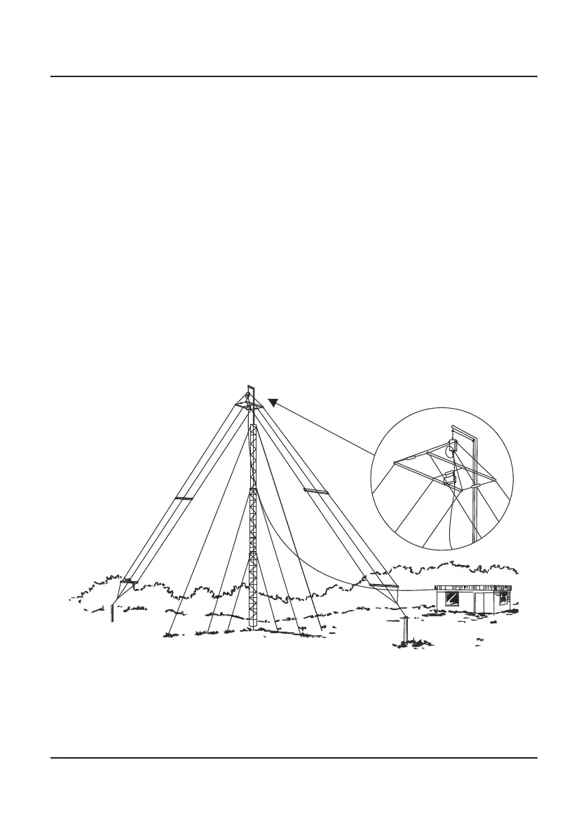
The Barrett 912 antenna can be mounted either in a horizontal or inverted ‘V’
conguration as illustrated in the following diagrams. In the horizontal con-
guration, the major radiation direction is broadside to the antenna. When
mounted in the inverted ‘V’ conguration, the antenna becomes fairly omni-di-
rectional. In the horizontal conguration, the minimum distance between the
masts is 32 metres and the recommended mast height is 15 metres. In the
inverted ‘V’ conguration the recommended mast height is 15 metres and
at this height the 2 metre stub masts are each installed at a minimum of 19
metres from the mast base. In this conguration the mast must have an offset
or out-rigger bracket, at least 0.8 metres long, to hold the antenna away from
the mast. Support towers may be either lattice masts as illustrated, tubular
telomasts or other support structures that may be available locally. It is recom-
mended that the halyards used to support the antenna be either UV stabilised
Dacron cord or wire rope and that pulleys should be of stainless steel construc-
tion.
Install the antenna as illustrated in the diagrams, in the inverted ‘V’ congura-
tion the eye on the top of the balun is used to attach the support halyard. In the
horizontal conguration the balun hangs below the antenna.
As with all antenna installations ensure the antenna is as far from sources of
electrical interference as possible and in a position that makes it impossible for
the antenna to come in contact with high voltage overhead mains wiring.