HB-37420-810-01-25F-EN SMX100 Installation manual.docx Page 105 of 260
Version: 25F
4.3.4 Digital Outputs
The modules
• SMX100-1(/2), SMX100-2(/2), SMX100-4(/2)
• SMX111(/2/D), SMX111-2(/2/D), SMX112(/2/D), SMX112-2(/2/D)
• SMX131x(/2), SMX132-x(R)/2/D
all have basic outputs of identical design.
4.3.4.1 Characteristic data of the basic outputs
The SMX-Serie provides a total of 8 outputs, which can be interconnected individually or in
groups.
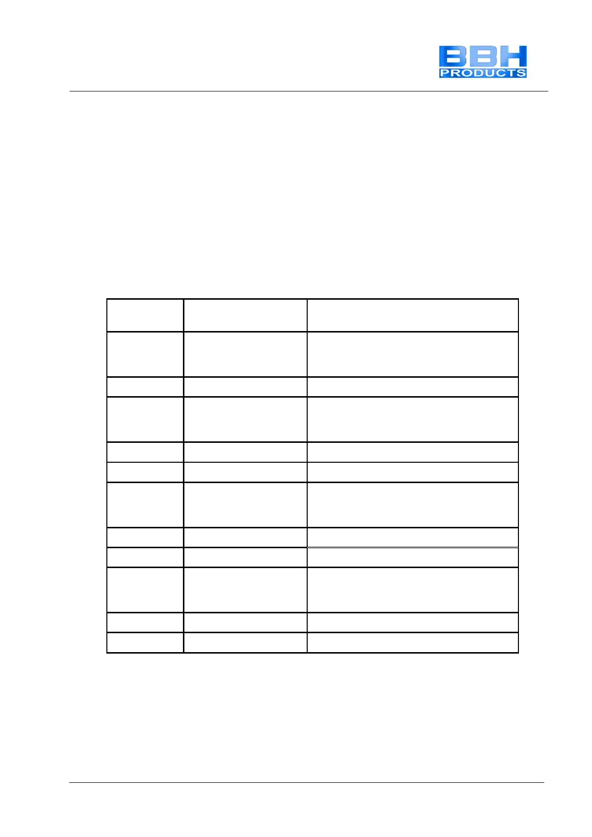
Architecture acc. to
EN ISO 13849-1
Combination
of 2 relays Q
5 to Q 6
Complete tripping channel in compliance
with architecture category 4 acc. to EN
ISO 13849-1
Complete tripping channel in compliance
with architecture category 4 acc. to EN
ISO 13849-1
Complete tripping channel in compliance
with architecture category 4 acc. to EN
ISO 13849-1
Complete tripping channel in compliance
with architecture category 4 acc. to EN
ISO 13849-1
The Qx_PP, Qx_PN and Qx- outputs are subjected to a plausibility test in all operating states. In
switched on state the correct function of all outputs is tested with a cyclic test pulse. For this
purpose the output is switched to the corresponding inverse value for a test period TT <500µs
(typically 200 µs) i.e. one P-output is switched instantaneously to 0 VDC potential, while one M-
output is switched to 24 VDC potential.
The relay outputs are monitored for plausibility during each switching cycle. The relay outputs
must be switched cyclically and thus tested to maintain the safety function. The switching/test
cycle is determined in dependence on the application.
 Loading...