AR6201-(X0X)
Page 1-2 DV 14300.03/.04 Issue 5 5/2013
All controls and indicators are located on the front panel. The
equipment connectors and the antenna socket are located at the rear of
the unit. On the right-hand side is a Circuit Breaker located.
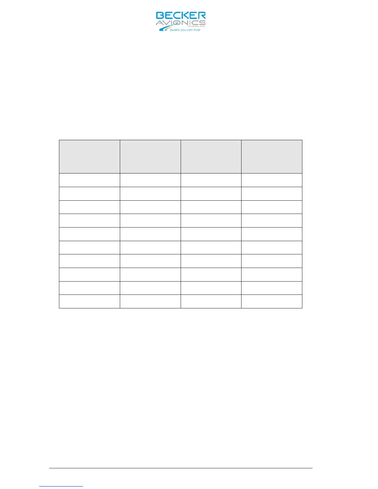
Frequency Indication
By means of a liquid crystal display (LCD) the frequency indication is
provided. The required operating frequency is set with the rotary knob.
The relation between the real operating frequency and the displayed
frequency is according to standards (ED-23B, chapter 1.3.2). For an
overview, refer to the table below.
Operating
Frequency (MHz)
Channel Spacing
(kHz)
Displayed
Frequency
in 8.33+25 kHz
Displayed
Frequency
in 25 kHz Mode
118.0000 25 118.000 118.00
118.0000 8.33 118.005 N/A
118.0083 8.33 118.010 N/A
118.0166 8.33 118.015 N/A
118.0250 25 118.025 118.02
etc. etc. etc. etc.
136.9750 25 136.975 136.97
136.9750 8.33 136.980 N/A
136.9833 8.33 136.985 N/A
136.9916 8.33 136.990 N/A
Audio Outputs
The transceiver includes two audio outputs: headphone and speaker. The
headphone rated output power is 300 mW into 150 Ohm. The rated output
power from the speaker output is 4 W into 4 Ohm.
Mike Inputs
The VHF transceiver has an input for dynamic microphone (DYN_MIKE) and
an input for standard microphone (STD_MIKE). Each input is able to
operate with single microphone or with 2 microphones of the same type
connected in parallel.
AF Auxiliary Input
The AF auxiliary input enables to connect an external audio source (NAV,
music-player …) to the transceiver. The external audio is audible only
when the transceiver is in Receive Mode.