AR6201-(X0X)
Page 2-36 DV 14300.03/.04 Issue 5 5/2013
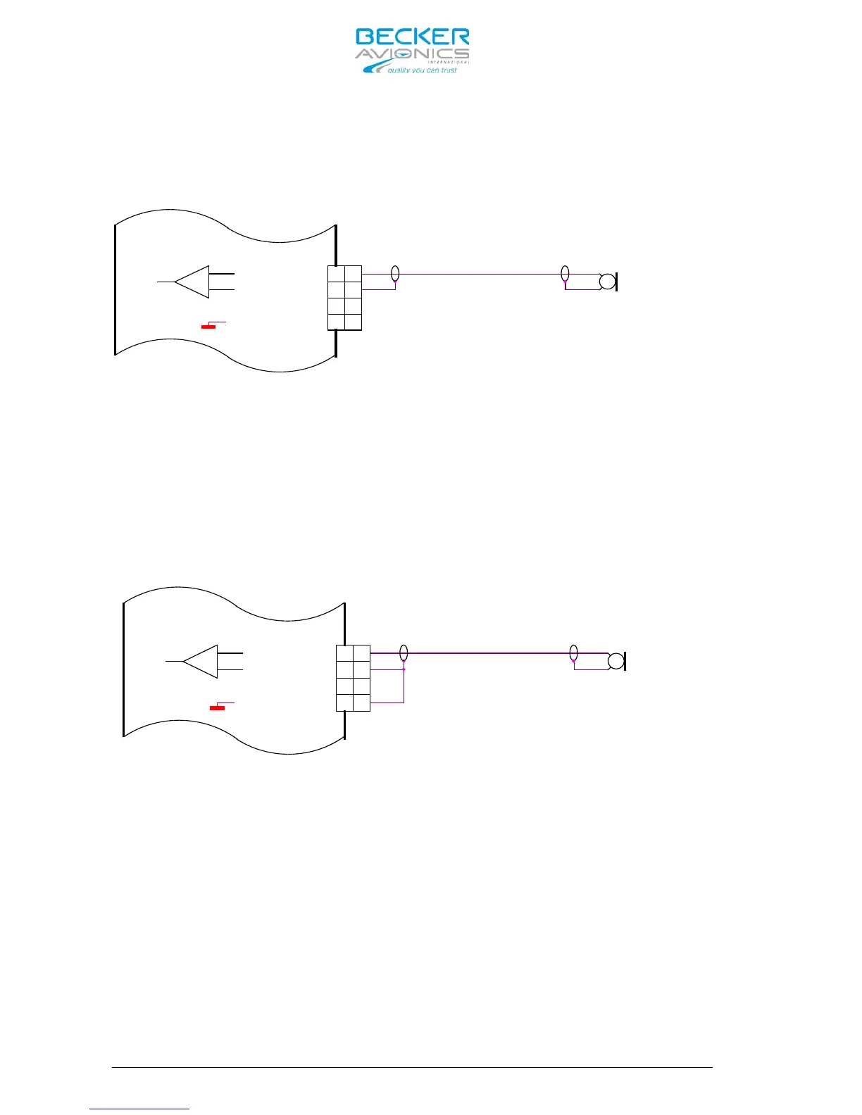
2.10.2 Dynamic Microphone Input
Retrofitting an AR4201 with the AR6201-(X0X) in a typical glider
installation with a dynamic microphone is shown below:
Dynamic Mike
18
6
5
8
MIKE_STD_LO
MIKE_DYN_LO
MIKE_STD_HI
6
5
MIKE_DYN_HI
8
18
Figure 2-13 AR6201 with already existing interwiring for AR4201
Connect the cable shielding to pin P1-6, which is the low side input for
dynamic microphone. Because in AR6201-(X0X) this input is balanced, the
cable shield is not any more connected to ground (like it was case with
the AR4201). In most cases, it is not a problem. Carrying out the
following modification is recommended if interference with microphone
signal occurred:
Connect Pin P1-6 with Pin P1-8 (the cable shield is grounded). See
Figure 2-14.
Dynamic Mike
5
8
18
6
MIKE_STD_LO
MIKE_STD_HI
MIKE_DYN_LO
MIKE_DYN_HI
5
6
18
8
Figure 2-14 Modified Dynamic Microphone interwiring for AR6201
2.10.3 Temperature Sensor
The AR6201-(X0X) has no temperature sensor input, but a temperature
sensor connected between pin P1-8 and pin P1-20 (from previous
installation) has no impact to the operation of the transceiver.
2.10.4 RS-232 Interface
The AR6201-(X0X) has no RS-232 interface for remote control, but a RS-
232 signal connected to pin P1-9 or pin P1-22 (from previous
installation) has no impact to the operation of the transceiver.
2.10.5 AFCU/AGC/AFWB
Normally not used in aircraft installations are Pin P1-15 and Pin P1-16.
Different functions of these pins will not cause any trouble when
retrofitting an AR4201.