34
16. Ifthesystemtestfailed,followthediagnostictipstocorrect:
a. Ensure that all connections on the Test Line Assembly are made as directed.
b. EnsuretheNOxFlowsensorisorientatedwiththeairowinthedirectionofthe
arrowmarking,thedoseportionclosesttothesampleendofthetestline.
c. EnsurethevalvesareopenonallNOsupplycylinders.
d. Checktheairowissetto10L/min.
17. Ifthesystemtestfailsasecondtime,theunitcannotbeusedforintelligentautomated
delivery.CalltheSystemEngineer,andreplacethesystem.
18. Oncethesystemtesthaspassed;shutofftheO
2
ow,anddisconnectthetestedLine
Assemblyfromthesupplyline.TheveriedLineAssemblyisreadytoconnectintothe
patientventilatorcircuit
If the NOxBOX
i
system is not to be used within next 10 minutes, turn
off the cylinder valves, detach the supply lines from Port 1 and Port
2, and release the line pressure using the purge needle at the back of
the monitor. Then re-attach the supply lines to Port 1 and Port 2.
WARNING: If the NOxBOX
i
system is left pressurized for more than 10
minutes while not in use, repeat the system test. Connect the Line
Assembly to the air supply as described in steps 11-17. Press Next.
The system test will run automatically.
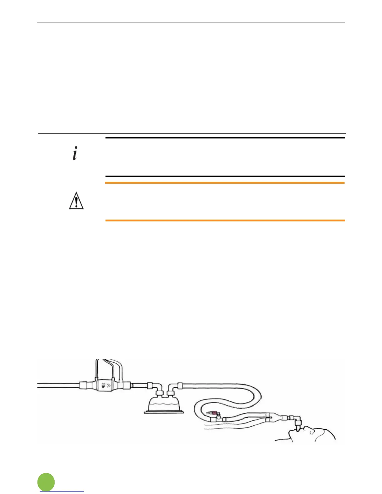
Ventilator inspiratory limb showing NOxFlow placement before humidier.
19. Connect the NOxBOX
i
tothepatientventilatorinspiratorylimb.SeeSection5.3onwardsfor
Patient Circuit connection diagrams.
The sample point adaptor should be connected immediately behind the patient Y-piece on
theinspiratorylimb.Toachieveconsistentresults,placeaone-wayuttervalvebetweenthe
sampleconnectorandtheY-piecetopreventcontaminationofthesamplefromexhaled
breath.
20 . Connect the upstream end of the NOxFlow sensor to the upstream inspiratory limb tubing
TheNOxFlowshouldbesituatedupstreamofthehumidier.
Maintaintheoptimum1mdistanceofventilatortubebetweenthesamplepointandthedose
introductionpointontheNOxFlowforbestperformance(between0.7and1.3misideal).
The system is now ready for dose entry and alarm setting procedures.