QTERM-G55 Terminal Supported Interfaces
Qlarity-Based Terminal Hardware 41
The following table shows the pinouts for each type of serial interface.
Power is supplied to the terminal through pin 9 and ground is supplied through pin 5 of the pri-
mary serial port connector. System ground is also connected to pin 5 of the secondary serial
port connector.
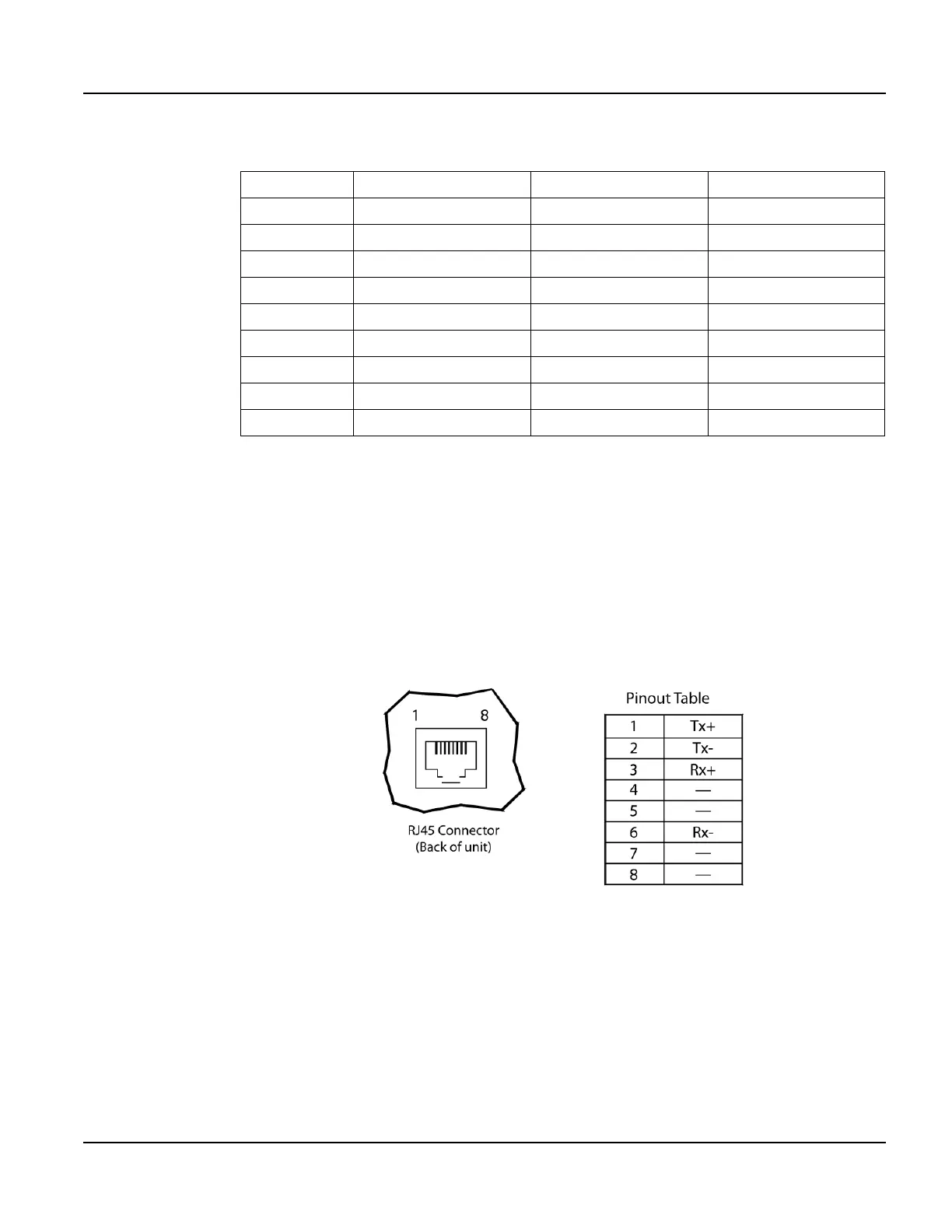
3.2.2.1 Optional Ethernet Port (Panel-mount)
The optional Ethernet port has a standard 10Base-T interface with an 8-pin (RJ-45) modular
jack connector and uses TCP/IP protocol.
The connector orientation and pinout table are shown in Figure 19.
3.2.3 Optional Power-over-Ethernet Module
The optional Power-over-Ethernet module allows the user to provide power and communica-
tions to the QTERM-G55. The power can be provided from an IEEE 802.3af compliant hub or
switch as well as from a standard power supply.
Pin 232 422 485
1 — Tx- RTx-
2Tx Tx+ RTx+
3Rx Rx+ —
4— — —
5 Ground Ground Ground
6— Rx- —
7CTS (in) —
8RTS (out) —
9Power Power Power
Figure 19
QTERM-G55 Ethernet Port Pinouts