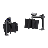
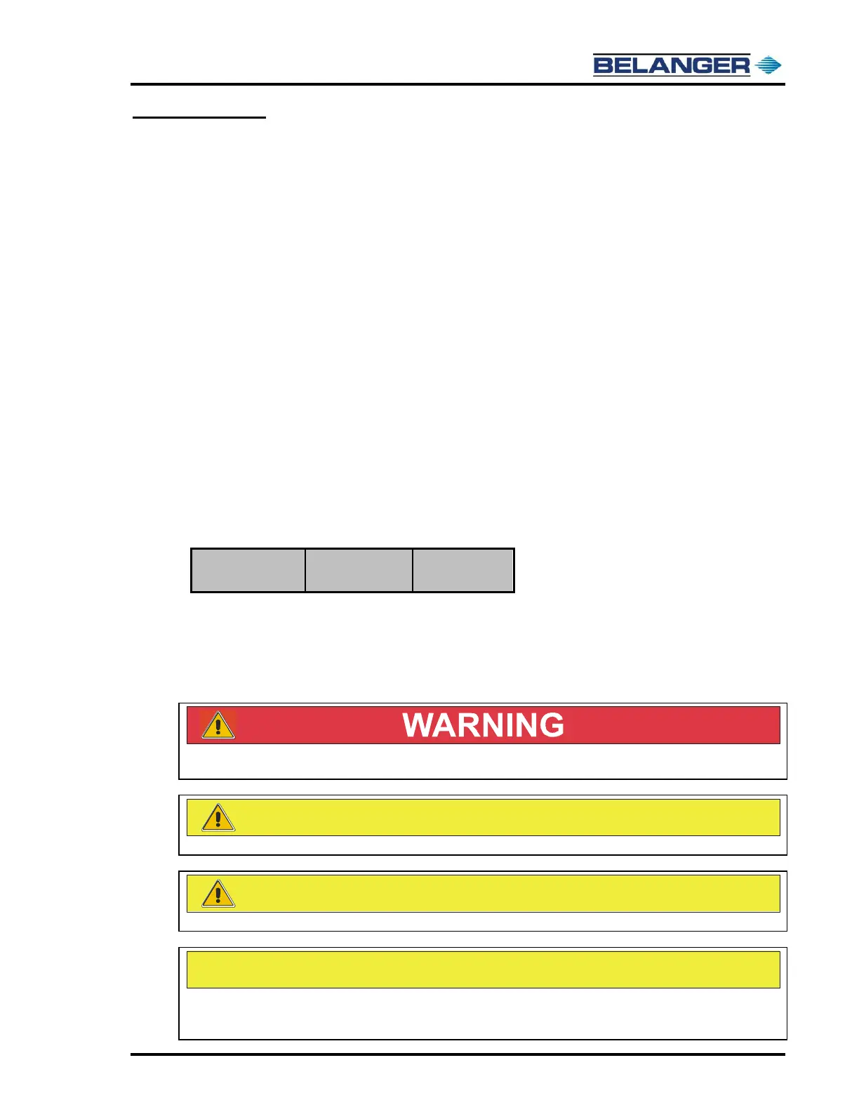
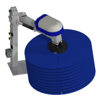
SpinLite® Full Side Washer
1MANUL961 Belanger, Inc. * PO BOX 5470 * Northville, MI 48167-5470 * Ph (248) 349-7010 * Fax (248) 380-9681 9
Specifications
Requirements
Physical
Tunnel space: required driver side
Tunnel space: required passenger side
Two 1 HP, 3-Phase Motors, terminated in Junction Box at the top of the Leg. See the chart
below for requirements.
Two 24V Signal Wires from the configured LED SpinLite Lighting Panel, terminated at the
Junction Box at the top of each Leg Assembly
One 110V Control Wire terminated at Supplied Pneumatic Control Panel
One 1/2” poly-flow tube for Chemical/Water, Tee’d to feed driver and passenger side SpinLite®
Full Side Winder assemblies, terminated at Water Manifold on each Leg Assembly
Water Output: 6 GPM total (Two Nozzles per side: 1.5 GPM x 65°@ 40 psi per Nozzle)
One 1/4” poly-flow tube Main Pneumatic feed to Air Panel (1CFM)
Four 1/4” Airlines for Extend and Retract of the Arm Cylinders on each SpinLite® Full Side
Washer® Assembly
DISCONNECT AND LOCKOUT ELECTRICAL POWER BEFORE SERVICING ANY
EQUIPMENT!
Always wear safety glasses when performing maintenance on any equipment.
It is recommended that a licensed electrician is contracted to perform all electrical installations.
A compressed Air System should be set correctly to support 90 PSI necessary to operate equipment,
but should never be set to deliver more than 120 PSI air pressure to the Belanger specified
equipment.