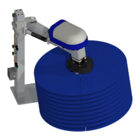
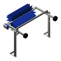
SpinLite® Full Side Washer
1MANUL961 Belanger, Inc. * PO BOX 5470 * Northville, MI 48167-5470 * Ph (248) 349-7010 * Fax (248) 380-9681 1
Table of Contents
Belanger Incorporated Limited Warranty .............................................................. 3
Operational Warning ............................................................................................... 4
Important Safety Information ................................................................................. 5
Safety Symbols and Signal Words .................................................................................................................................. 5
IMPORTANT Safety Information – MUST READ ............................................................................................................ 6
Introduction ............................................................................................................. 7
Before You Get Started ................................................................................................................................................... 8
Specifications .......................................................................................................... 9
Requirements .................................................................................................................................................................. 9
Physical .......................................................................................................................................................................................... 9
Utility ............................................................................................................................................................................................... 9
Electrical ......................................................................................................................................................................................... 9
General Dimensions ...................................................................................................................................................... 10
Inspection .............................................................................................................. 11
Equipment to Inspect Before Installation ....................................................................................................................... 11
Installation ............................................................................................................. 13
Identify Conveyor .......................................................................................................................................................... 13
Tunnel Placement: Overview ........................................................................................................................................ 14
Standard, Stand-Alone Configuration .......................................................................................................................................... 14
Staggered, with QuickFire® Plus assemblies .............................................................................................................................. 15
Tunnel Placement: Preparation ..................................................................................................................................... 16
Tunnel Placement: Stand-Alone Installation ................................................................................................................. 16
Tunnel Placement: Staggered Installation with QuickFire® Plus .................................................................................. 18
Attach the Arm Assemblies ........................................................................................................................................... 20
Install the Drive Shaft Components ............................................................................................................................... 24
Connect the Motor/Gearbox and Slip Ring to the Drive Shaft ....................................................................................... 27
Connect LED Power Cable to Slip Ring ........................................................................................................................ 31
Install Hub Assemblies, LED Lights with Electrical Connections & ShineMitts™ .......................................................... 32
Attach Hub Assemblies to Drive Shafts ....................................................................................................................................... 32
Hub LED Installation and Electrical Connections ......................................................................................................................... 35
Load ShineMitts™ on Hub Assemblies ........................................................................................................................................ 37
Connect LED Lights to Wire Harness .......................................................................................................................................... 42
Filler Strip Installation for the SpinLite® FSW Assemblies ............................................................................................ 44
Utilities ........................................................................................................................................................................... 46
Water Connections: Water Line to the SpinLite® Full Side Washers .......................................................................................... 46
Pneumatic Connections: Air Panel to Cylinders ........................................................................................................................... 48
Electrical Connections: Air Panel to Controller ............................................................................................................................ 50
Pneumatic Connections: Initial Air Settings for Air Panel ............................................................................................................ 51
Electrical Connections: Main Power to Motors and LED Lights ................................................................................................... 52
Electrical Connections: Motor....................................................................................................................................................... 53