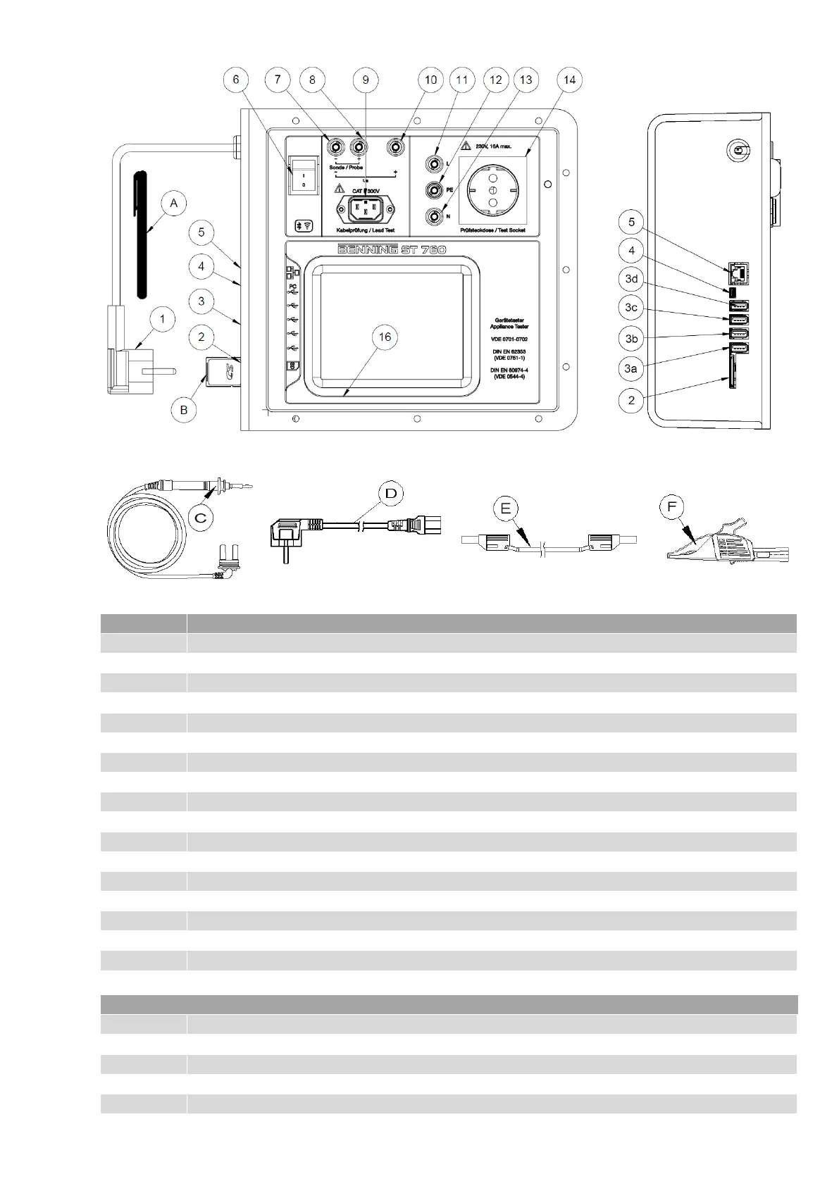
BENNING ST 760, plan view (without case)
View of connection side
(without case)
Measuring accessories included
Meaning of operating elements:
USB 2.0 interface, socket type A, e. g. for USB sticks (max. 8 GB), keyboard
USB 2.0 interface, socket type A
USB 2.0 interface, socket type A
USB 2.0 interface, socket type A
USB 2.0 interface, socket type Mini B
Jack, black (-), measuring jack (for test probe, SELV/PELV, open-circuit voltage (Ua))
Jack, black (+), measuring jack for test probe
Cable adapter jack (for cable test)
Jack, red (+), measuring jack (for SELV/ PELV, open-circuit voltage)
Jack, black, "L", can be connected to the test socket
Calibration jack, yellow/green, "PE", hard-wired to the test/mains socket
Jack, blue, "N”, can be connected to the test socket
Switchable test/mains socket
1x touchscreen stylus / input stylus
1x safety test probe with 4 mm safety jack
1x cable adapter (for cable testing)
2x measuring line (test cable) (1.5 m) with 4 mm safety plug
2x alligator clip with 4 mm safety jack