63
16 Optional single measurements:
16.1 Three-phase measurement
Explanation
The three-phase measurement is intended to check three-phase
loads and supports the following measurements:
continuity test of the protective conductor system
insulation test
measurement of the protective conductor current and contact
current using the following methods:
differential current measurement
direct current measurement
alternative leakage current measurement
functional test
The following measuring adapter is required to carry out the three-
phase measurement:
BENNING MA 2-16
Measuring adapter for
three-phase loads; max.
3x 16 A (AC 1) CEE 5-pin
Start of test
First start the test on your tester (orange lamp on the
BENNING MA 2-16 lights up) and only then switch on
your test sample!
End of test
First switch off the test sample and then finish the test
on your tester. Non-compliance with this sequence
might result in damage to or destruction of the
BENNING MA 2-16 measuring adapter in the event of
extreme starting currents of your test sample or
inductances in the circuit.
Before carrying out the functional test and all tests for
which the test sample is supplied with mains voltage
and put into operation, it must be proved that there are
no short-circuits in the test sample within phases L1,
L2, L3 and the neutral conductor N.
The maximum admissible thermal continuous current is
always 16 A AC per phase.
The device may only be connected to a TN, TT or IT
power supply network with max. 240 V/ 400 V, which
complies with the applicable safety regulations (e. g.
IEC 60346, VDE 0100) and is protected with a
maximum nominal current of 16 A.
Please observe and follow all instructions of the
BENNING MA 2-16 operating manual.
The adapter may only be used for testing devices with a
5-pin CEE plug and a maximum current consumption
of 3 x 16 A (AC-1).
During insulating resistance or alternative leakage
current tests, all of the three phases L1, L2, L3 and the
neutral conductor N of the test sample are shorted.
When testing the protective conductor resistance, the
value of the measured resistance increases by the
share caused by the protective conductor system of the
BENNING MA 2-16 measuring adapter.
In case of measuring results near the admissible RPE
limit, measure the RPE of the measuring adapter at the
PE connection of the CEE socket and subtract it from
the measured value of the previous measuring result.
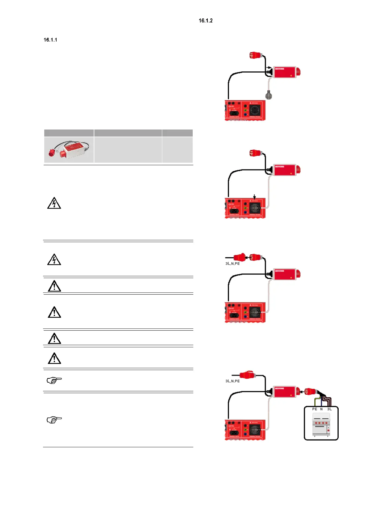
Application
Before starting a three-phase test, the following steps are necessary
to connect the measuring adapter:
Connection conditions of the BENNING MA 2-16
Connect the mains connection cable of your tester to the shock-
proof socket marked “Mains supply PAT tester" of the
BENNING MA 2-16.
Connect the shock-proof cable of the BENNING MA 2-16 to the
test socket/ mains socket of the tester.
The connection on the BENNING MA 2-16 is marked
"to test/mains socket PAT tester”.
Plug the CEE connection cable of the BENNING MA 2-16 into an
appropriate CEE socket 16 A/ 6h of your electrical installation.
The connection on the BENNING MA 2-16 is marked
“3~/ N/ PE, 400 V, 50-60 Hz, 16 A”.
From this moment on, the BENNING MA 2-16 and your tester are
supplied with electric power.
Connect your test sample to the CEE socket of the
BENNING MA 2-16. The socket is marked with the designation
“Test/mains socket test object 16 A”.
You can now start the test.