Density Meter LB 444 SECTION 2. SYSTEM DESCRIPTION
19
Product Data
Enter the product data for calibration separately for each product.
Product Selection
No. 1/2/3/4:
Enter the product number for calibration.
Current Output :
Select the start value 0 or 4 mA of the current output signals (26a/26c).
Current Output Limit Values:
0/4 mA: Enter the lower density or concentration values in the defined unit (see sk1 Cali-
brate).
20 mA: Enter the upper density or concentration values in the defined unit (see sk1
Calibrate).
Current output error:
Current: VALUE/HOLD
Value:
You can select this if the last measured value should be held in case an error is
detected ("HOLD"), or if an arbitrarily selected value between 0 and 22 mA
should be set. The requested value has to be entered after selecting "VALUE".
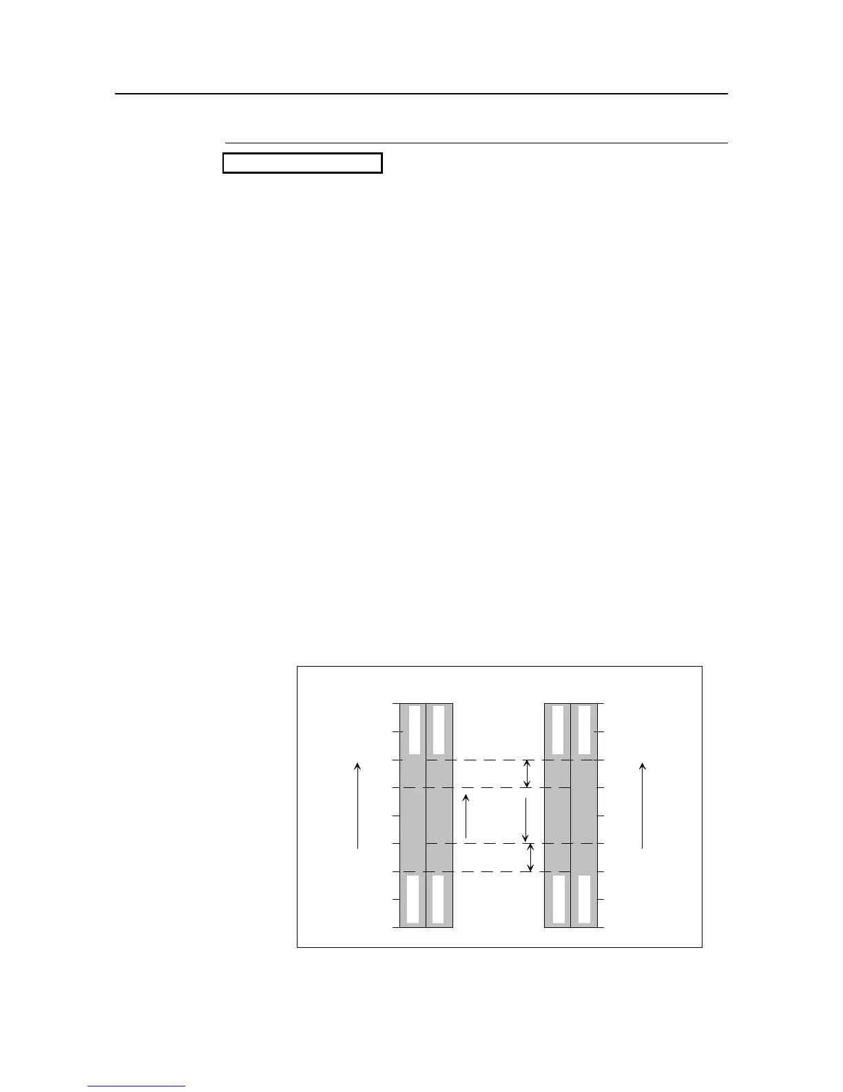
Relay No. 2 Setup:
Minimum/Maximum:
Hysteresis %:
Enter the relay break-over point within the selected density measuring range.
Depending on the setting as Max. or Min. function, the relay is de-energized
(circuit opening connection) when the selected value is exceeded or not
reached. If the displayed value drops again, the relay picks up again, delayed
by the value of the selected hysteresis. The switching hysteresis should be
about 5%.
Rel.
min.
1.0
1.2
1.4
1.6
1.8
Rel.
min.
Rel.
max.
Rel.
max.
3