Density Meter LB 444 SECTION 4. CONNECTIONS
37
4.2
Evaluation Unit LB 444
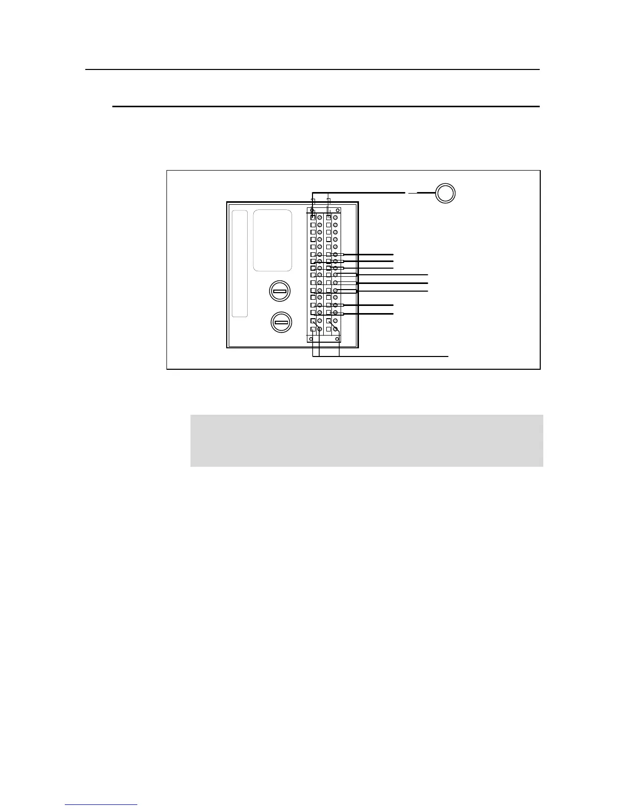
Make the connections on the rear panel of the evaluation unit as shown in the wiring
diagram in the appendix to this manual.
LB 444
Detector
Mains supply
Fuse
ca
2
4
6
8
10
12
14
16
18
20
22
24
26
28
30
32
Relay 1
Relay 2
Relay 3
Dig. In 2
Dig. In 3
Current In (+/-)
Current Out Density (-/+)
1(+)
2(-)
Voltage
selector
Dig. In 1
Figure 22: Terminal connection evaluation unit (rear panel)
Carefully note the power supply for the instrument and observe all safety
provisions regarding the power supply. Separate fuse protection and an
easy to access power switch must be provided as part of the installation,
since the evaluation unit does not include its own mains switch.
Refer to the wiring diagram in the appendix to this manual for the connections.
The terminals are described as follows:
Detector Terminal (2a/2c)
Connection is made via 2-wire technique; the detector protection type is EEx de
IIC T6 or EEx de (ib) IIC T6 or EEx de (ib) IIB T6. For inherently safe installation,
the cable ends on the strip terminal must be protected by a 10 mm long shrink
tube.
Terminal for Relay 2 (12a/12c)
The relay can be used as Max. or Min. relay depending on the software configu-
ration and the setting of the break-over point.
Terminal for relay 3 (14a/14c)
The relay can be used as Max. or Min. relay depending on the software configu-
ration and the setting of the break-over point.