1 2 3
4
September 2021
Installation, Operation and Maintenance Manual
VCIOM-01249-EN Rev. 0
Installation12
Section 3: Installation
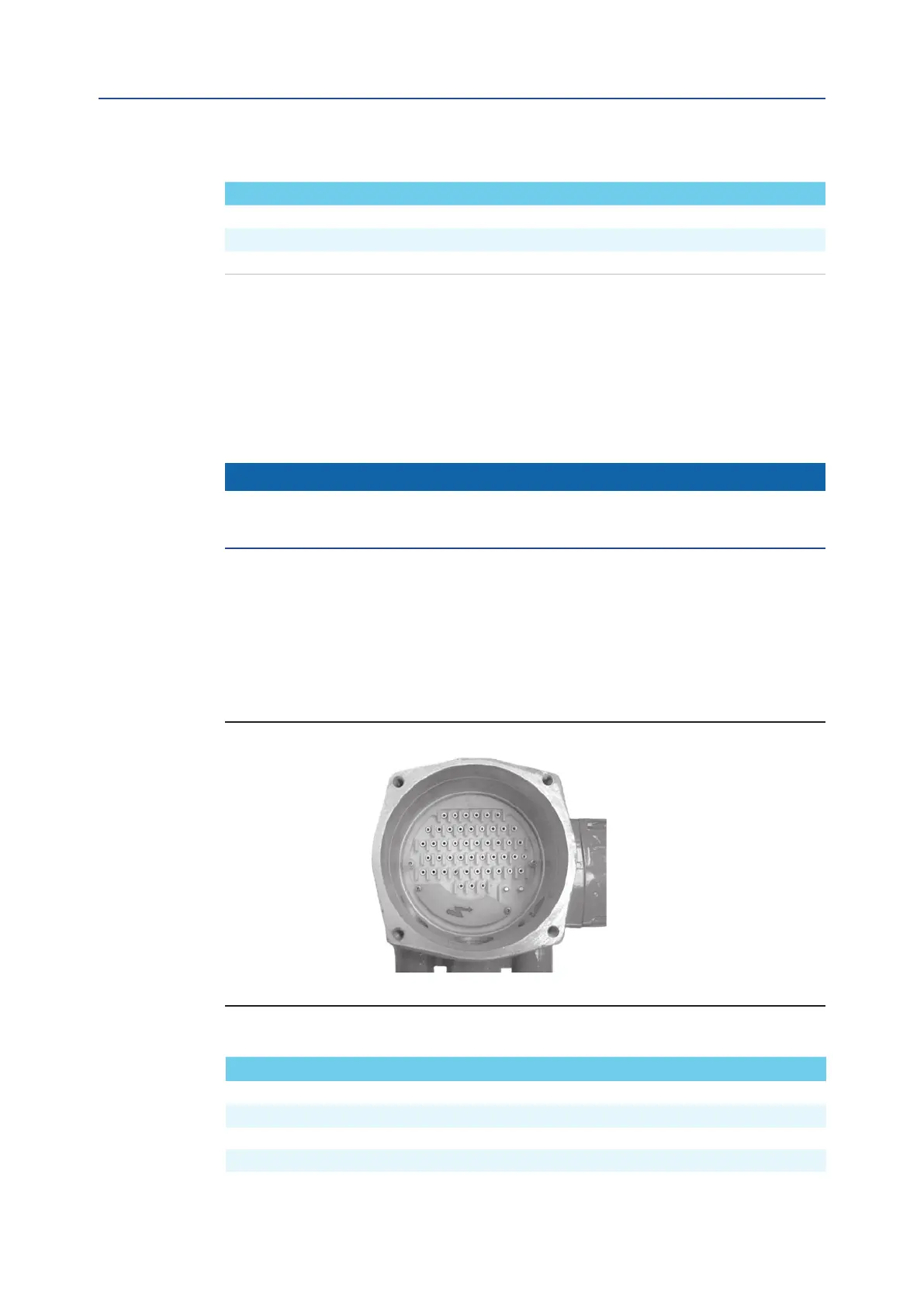
Figure 12
Model Tightening torque (Nm)
F01-2000/150 40
F01-2000/300 40
F01-2000/600 80
Table 4.
Entry NPT size Tightening torque (Nm)
1 1" M32x1.5
2 1 - 1/2" M40x1.5
3 1" M32x1.5
4* 3/4" M25x1.5
Table 5.
3.5 Electrical Connections
Before powering to the actuator check that the supply voltage details on the nameplate
are correct for the plant. Access to terminals for electrical connections and commissioning
is through the terminal cover since all settings are non-intrusive. The removal of any other
covers without Bif’s approval will invalidate the warranty.
Bif will not accept any responsibility for any damage or deterioration that may be caused.
NOTICE
All the accessories (in particular cable glands) must be certied according to
94/9/EC Directive.
3.5.1 Identication of Entries
Electric actuators series F01-2000 are equipped with 4 entries (3 are standard the fourth is
supplied when requested).
With reference to Figure 12, the thread form/size for entry is as follows:
NOTE:
* optional