30 support@cedarsummitplay.com
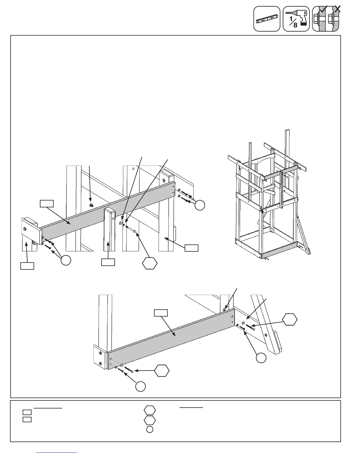
Note: Pre-drill all holes using a 1/8” drill bit before installing the lag screws.
E:Attach(2033)MKMountto(1906)TopFrontBackusing1(H12)1/4x2”HexBolt(withlockwasher,at
washerandt-nut).(g.13.4and13.6)
F:Makesure(1906)TopFrontBackislevelandthenattachtoboth(1931)Postsusing4(S7)#12x2”Pan
Screws(with3/16”atwashers).(g.13.4)
G:Attach(1768)LowerBacktothebottomof(1931)Postswith2(LS3)1/4x3”LagScrews(withatwasher)in
thetop(pre-drilled)holesand2(S7)#12x2”PanScrews(with3/16”atwashers)inthebottomholesasshown
ing.13.5and13.6.
Step 13: Back Wall Assembly
Part 2
Wood Parts
Hardware
Fig. 13.4
1 x 1/4 x 3” Hex Bolt (1/4” lock washer, 1/4” at washer, 1/4” t-nut)
2 x 1/4 x 3” Lag Screw (1/4” at washer)
6 x #12 x 2” Pan Screw (with 3/16” at washer)
1 x Top Front Back 1 x 4 x 38-1/2”
1 x Lower Back 1 x 5 x 38-1/2”
1906
S7
H12
LS3
1/4”Flat
Washer
1-4”
T-Nut
Fig. 13.5
Fig. 13.6
S7
LS3
1768
1768
S7
LS3
1/4”Flat
Washer
1-4”
T-Nut
H12
with3/16”
FlatWasher
S7
with3/16”
FlatWasher
S7
1/4”Lock
Washer
1931
2033
1906
1931
Back
with3/16”
FlatWasher
with3/16”
FlatWasher