27 support@cedarsummitplay.com
Fig. 11.1
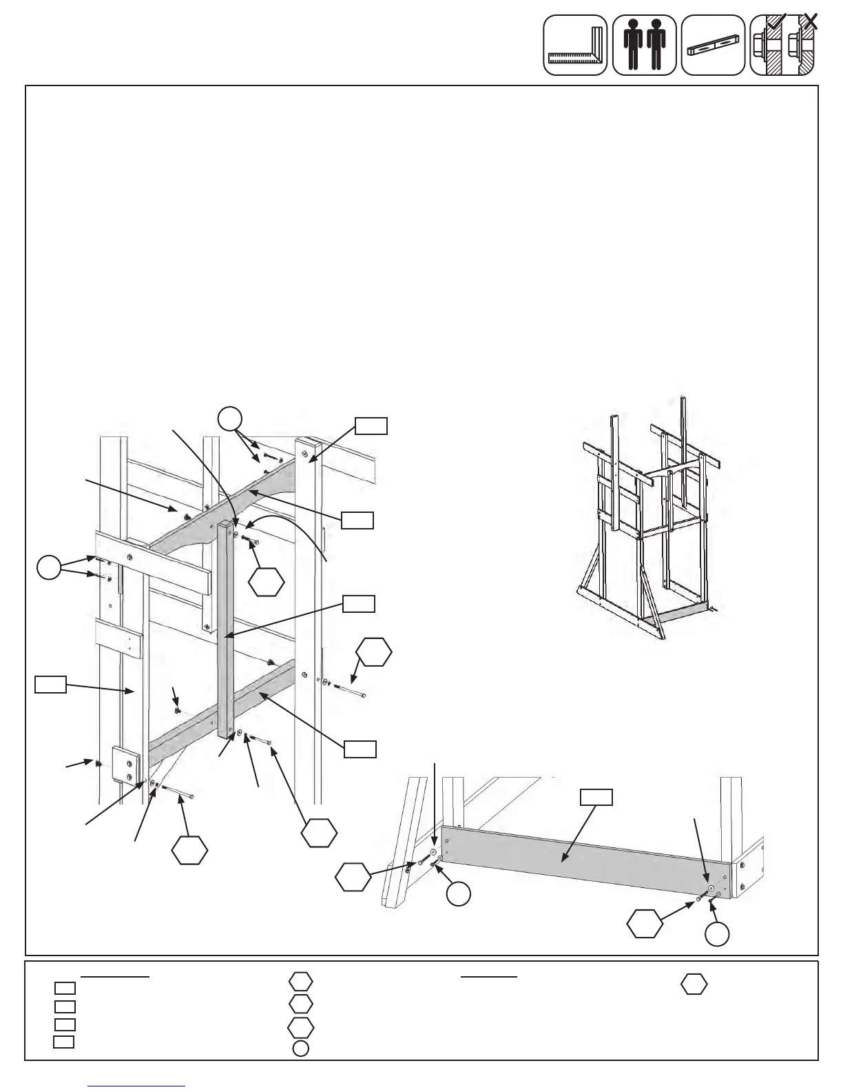
Step 11: Front Frame Assembly
A:Onthefrontsideoftheassembly,fromtheinside,attach(1908)FrontFloortoeach(1931)Postwith2(H6)
1/4x4-3/4”HexBolts(withlockwasher,atwasherandt-nut).(g.11.1and11.2)
B: Flushtothebottomof(1908)FrontFloorattach(1937)CentreDividerwith1(H12)1/4x3”HexBolt(with
lockwasher,atwasherandt-nut).(g.11.2)
C:Attach(1937)CentreDividerto(2037)FrontTopusing1(H2)1/4x2”HexBolt(withlockwasher,atwasher
andt-nut).(g.11.2)
D:Makesure(2037)FrontTopissquareandlevelandthenattachtoboth(1931)Postsusing4(S7)#12x2”
PanScrews(with3/16”atwashers).(g.11.2)
Note: Pre-drill all holes using a 1/8” drill bit before installing the lag screws.
E:Attach(1768)LowerBacktothebottomof(1931)Postswith2(LS3)1/4x3”LagScrews(withatwasher)in
thetop(pre-drilled)holesand2(S7)#12x2”PanScrews(with3/16”atwashers)inthebottomholesasshown
ing.11.3.
Wood Parts Hardware
Fig. 11.2
Back
Fig. 11.3
1/4”Flat
Washer
1/4”Lock
Washer
1-4”
T-Nut
H2
1 x 1/4 x 2” Hex Bolt (1/4” lock washer, 1/4” at washer, 1/4” t-nut)
2 x 1/4 x 4-3/4” Hex Bolt (1/4” lock washer, 1/4” at washer, 1/4” t-nut)
1 x 1/4 x 3” Hex Bolt (1/4” lock washer, 1/4” at washer, 1/4” t-nut)
6 x #12 x 2” Pan Screw (3/16” at washer)
1 x Front Top 1 x 5 x 38-1/2”
1 x Centre Divider 2 x 2 x 31-3/4”
1 x Front Floor 2 x 3 x 38-1/2”
1 x Lower Back 1 x 5 x 38-1/2”
2037
S7
H2
H12
H6
1931
1908
1937
H6
with3/16”
FlatWasher
H6
with3/16”
FlatWasher
1931
2037
1937
1908
S7
S7
1/4”Flat
Washer
1/4”Lock
Washer
1-4”
T-Nut
H12
1/4”Flat
Washer
1/4”Lock
Washer
1-4”
T-Nut
1768
2 x 1/4 x 3” Lag Screw
(1/4” at washer)
LS3
S7
LS3
S7
LS3
with3/16”
FlatWasher
1/4”Flat
Washer
with3/16”
FlatWasher
1/4”Flat
Washer
CafeWall
FrontSwingWall
1768