33 support@cedarsummitplay.com
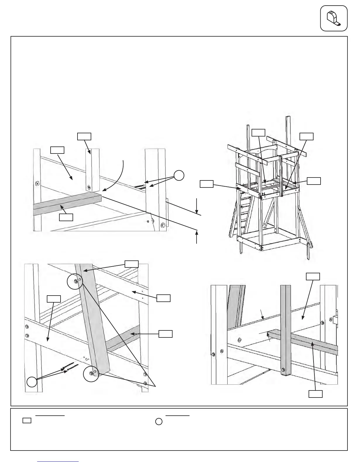
Step 16: Floor Frame Assembly
Part 1
A: Removethemiddleandbottomboltsin(2035)SWMount.Donotdiscardthesebolts,youwillre-installthem
afterthe(1903)FloorJoisthasbeenattached.(g.16.2)
B:Frominsideoftheassembly,measure2-3/4”downfromthetopof(1895)FloorEndand(2032)EndFloor
(g.16.3and16.4),thenattach(1903)FloorJoisttoeachboardusingthepilotholeswith2(S4)#8x3”Wood
Screwsperend.Makesurethereisa5/8”gapbetween(2031)RoofSupportand(1903)FloorJoist.(g.16.2
and16.4)
C:Reinstallthemiddleandbottomboltsin(2035)SWMountandtightenallthreebolts.(g.16.1)
Wood Parts
Hardware
Removethesebolts,
thenre-attachafter
joistisinstalled.
4 x #8 x 3” Wood Screw
1 x Floor Joist 5/4 x 3 x 38-1/2”
1903
S4
Fig. 16.2
Fig. 16.3
Fig. 16.1
Fig. 16.4
SwingWallSide
2-3/4”
S4
1895
2035
1895
1903
1761
1895
2032
1905
SwingWallSide
CafeWall
1903
S4
2032
2-3/4”
2034
5/8”Gap
1903
(hiddenbehindboard)
2031