39 support@cedarsummitplay.com
Wood Parts
Hardware
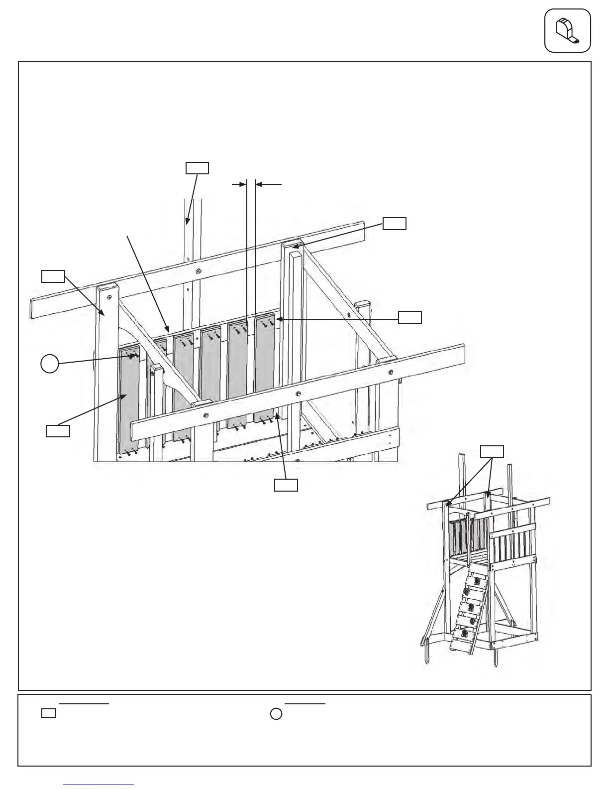
Step 21: Swing Side Wall Assembly
A: Inbetweenboth(1931)PostsonSwingWallsideattach6(1503)CedarWallsto(2034)WallSupportand
(1895)FloorEndusing4(S0)#8x7/8”TrussScrewsperboard.Thegapbetweenboardsshouldbeevenly
spacedat1”,notexceeding1-1/4”.Makesurethebottomoftheboardsaretightagainsttheoorboardsand
bevellededgesarefacingoutandareatthetopoftheboards.(g.21.1and21.2)
Note: Gaps between
boards evenly spaced at
1”, not to exceed 1-1/4”
Note:Someboardswere
removedforclarity
Bevellededges
towardstopand
facingout
24 x #8 x 7/8” Truss Screw
6 x Wall Board 1/2 x 4 x 20”
1503
S0
1931
2035
1931
1895
S0
x4per
board
Fig. 21.2
Fig. 21.1
1931
SwingWallSide
2034
Note: Evenly space 3 on
each side of SW Mount
1503
x6