29 support@cedarsummitplay.com
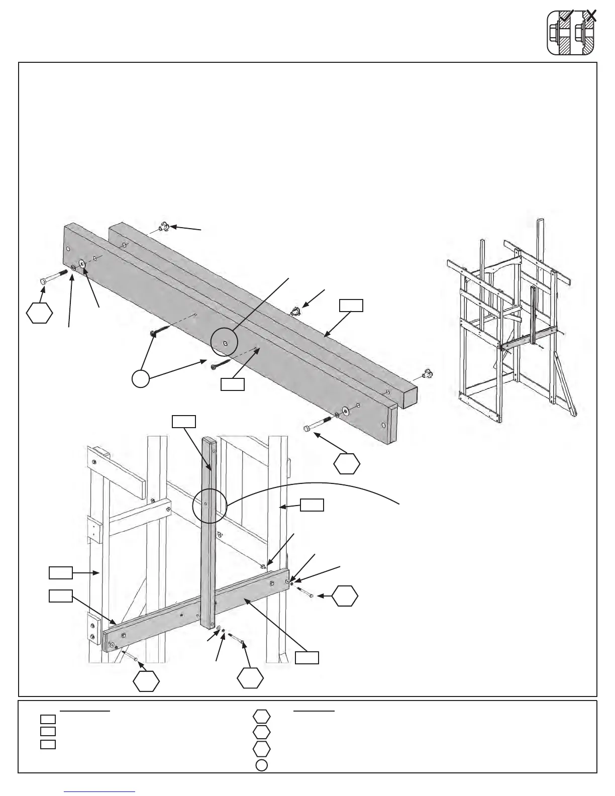
Step 13: Back Wall Assembly
Part 1
A:Attach(1894)BackFloorto(1761)SideJoistusing2(H3)1/4x2-1/2”HexBolts(withlockwasher,at
washerandt-nut)and2(S7)#12x2”PanScrewsasshowning.13.1.
B:Tapa1/4”T-Nutin(1761)SideJoistasshowning.13.1.
C: Onthebacksideoftheassembly,attach(1894)BackFloortoboth(1931)Posts,with(1761)SideJoiston
theinsideoftheassembly,using2(H5)1/4x4-1/2”HexBolts(withlockwasher,atwasherandt-nut).(g.13.2
and13.3)
D:Attach(2033)MKMountto(1894)BackFloorwith1(H13)1/4x3-1/2”HexBolt(withlockwasher,atwasher
andt-nut).(g.13.2and13.3).
Wood Parts
Hardware
Fig. 13.1
Fig. 13.3
Fig. 13.2
Notice hole
positioned down
Back
H3
2 x 1/4 x 2-1/2” Hex Bolt (1/4” lock washer, 1/4” at washer, 1/4” t-nut)
2 x 1/4 x 4-1/2” Hex Bolt (1/4” lock washer, 1/4” at washer, 1/4” t-nut)
1 x 1/4 x 3-1/2” Hex Bolt (1/4” lock washer, 1/4” at washer, 1/4” t-nut)
2 x #12 x 2” Pan Screw
1 x Side Joist 2 x 3 x 34-3/4”
1 x Back Floor 5/4 x 4 x 38-1/2”
1 x MK Mount 2 x 3 x 35”
1761
S7
H3
1761
S7
1/4”Flat
Washer
1/4”Lock
Washer
1-4”
T-Nut
H5
H13
2033
1894
1894
H3
1931
2033
1894
1761
1931
H5
H13
H5
1/4”Flat
Washer
1/4”Lock
Washer
1-4”
T-Nut
1/4”Flat
Washer
1/4”Lock
Washer
1-4”
T-Nut
Notice hole towards top.