C (E3) 08/2015 page 47/93
10.3 Zero-voltage relay alarm output
Collective alarm output via the zero-voltage relay alarm contact
2
incubator is equipped at the rear with a zero-voltage relay output
for temperature and CO
2
, which permits the transmission of alarms to an
external monitoring system in order to monitor and record the alarm signals.
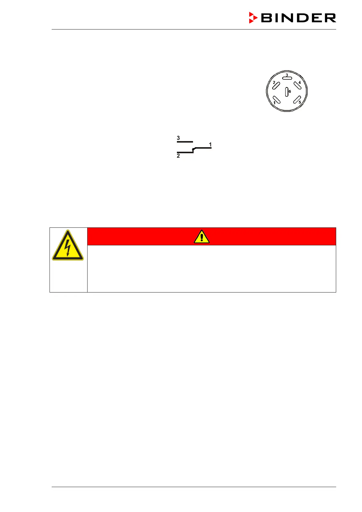
A DIN socket (15) serves to establish this connection.
Figure 22: Pin configuration of the DIN socket (15)
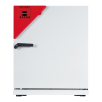
ALARM
Pin 2: Break relay
Pin 3: Make contact
In case there is no alarm, contact 1 closes with contact 3.
Closing contact 1 with contact 2 switches the zero-voltage relay alarm output.
The zero-voltage relay alarm output switches immediately, as soon as the red “ALARM” LED lights up on
the controller display. The zero-voltage relay alarm output switches for alarm instances listed in chap.
10.1 and in case of power failure.
Maximum loading capacity of the switching contacts: 24V AC/DC – 2.5 Amp.
DANGER
Electrical hazard.
Danger of death.
Damage to switching contacts and connection socket.
∅ Do NOT exceed the maximum switching load of 24V AC/DC – 2.5 Amp.
∅ Do NOT connect any devices with a higher loading capacity.
The alarm message on the controller display remains displayed during transmission of an alarm via the
zero-voltage relay outputs.
As soon as the cause of the alarm is identified and resolved, the alarm transmission via the zero-voltage
relay outputs resets automatically together with the alarm message on the controller display.
In case of a power failure, transmission of the alarm via zero-voltage relay outputs remains active for the
duration of the power failure. Afterwards, contact 1 will close automatically with contact 3.
Connection to an external monitoring system
To ensure short-circuit-proof alarm monitoring that will trigger the alarm when the C 170 is connected to
an external alarm monitor, connect the external alarm monitoring system to the C 170 via the contacts 1
and 3.