Repair work at the inner and outer chamber
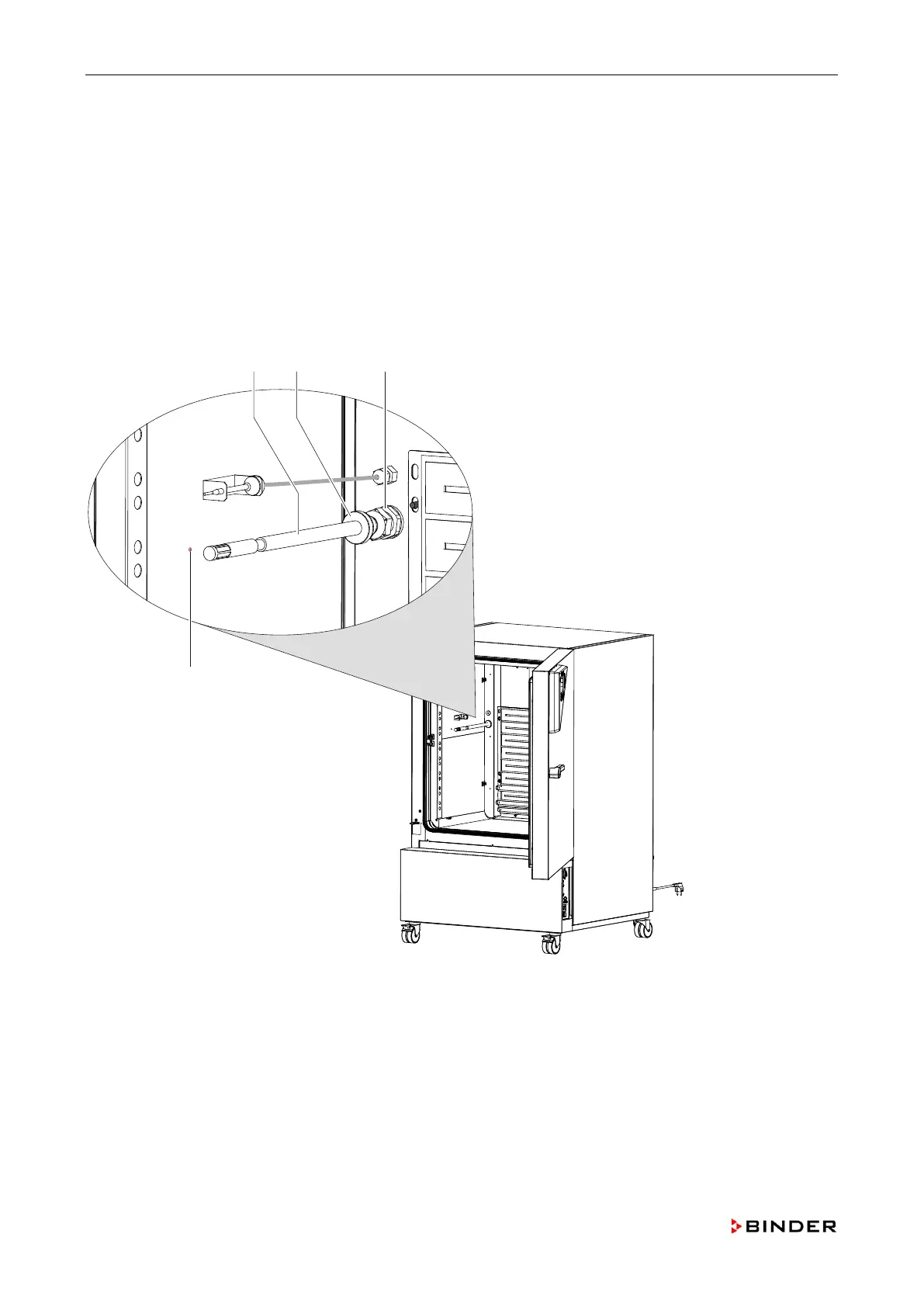
14. Remove with a cutter the insulating foam at the unit rear in the area of the humidity sensor.
15. Unscrew the nut of the screwed cable fitting (C) on the inside of the outer chamber.
16. Pull the humidity sensor (A) toward the rear out of the outer chamber.
17. Remove the sensor board of the humidity sensor (chap. 8.6).
18. Mount the new humidity sensor with its board by following steps 1 to 16 in reverse order.
19. When installing the sensor mind that the end of the humidity sensor fits the marking (D) on the outer
chamber.
20. After the installation fill the mounting opening on the rear with insulating foam.
21. Calibrate and adjust the humidity controller (chap. 11.5).
Figure 31: Replacing the humidity sensor and the sensor board (-3B2 )
A Humidity sensor
B Cable access port
C Screwed cable fitting
D Position marking
72 Service Manual KBF (E5.2) 04-2015