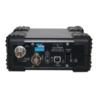
FlightHawk RF Test Set
A-8
sweep display area to indicate if the active signal is
within or outside the limits set by the limit line.
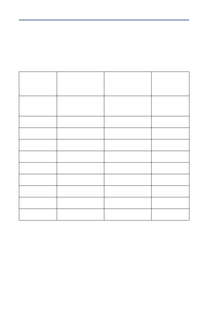
Table 1. TYPICAL RF SYSTEM FREQUENCY RANGE CHART
Cable and
Antenna System
Start/Stop Frequency
System Operating
Frequency
Maximum Voltage
Standing Wave
Ratio and (Return
Loss)
SATCOM
1500/1600 MHz (Rx)
1600/1700 MHz (Tx)
1525/1559 MHz (Rx)
1626.5/1660.5 MHz (Tx)
2.0
(9.54 dB)
TCAS 1020/1100 MHz
Transmit 1030/
Receive 1090 MHz
2.0
(9.54 dB)
ATC/DME
1000/1100 MHz
960/1220 MHz
1030-1090 MHz
2.0
(9.54 dB)
VHF 116/156 MHz 116/156 MHz
2.0
(9.54 dB)
VOR 108/118 MHz 108/118 MHz
6.0
(2.33 dB)
ILS (Localizer) 108/112 MHz 108/112 MHz
5.5
(3.19 dB)
ILS (Glideslope) 327/337 MHz 327/337 MHz
2.5
(7.36 dB)
Rad Alt (LRRA) 4200/4400 MHz 4275/4325 MHz
2.0
(9.54 dB
HF
1
1 HF DTF check does not test antenna. HF DTF check tests the cables from
HF Transceiver to the HF Coupler and the HF connection to the cables via
the Coupler Tray. When HF coupler is de-energized, it connects an internal
50 ohm load to the HF Transceiver RX/TX output. This facilitates testing
from the HF Transceiver without the need to access the Coupler. Test
connection of HF Coupler Tray to HF Antenna to structure using a bonding
meter.
1/100MHz 2/30 MHz
1.5
(13.98 dB)
Marker Beacon 74.85/75.15 MHz 75 MHz
1.5
(13.98 dB)