15
1.8 7 7. 87 7. 2 2 6 9 BLACKBOX.COM
NEED HELP?
LEAVE THE TECH TO US
LIVE 24/7
TECHNICAL
SUPPORT
1.8 77.87 7.2269
CHAPTER 2: OVERVIEW
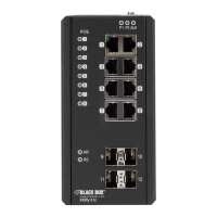
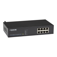
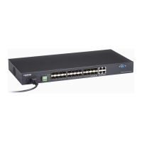
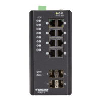
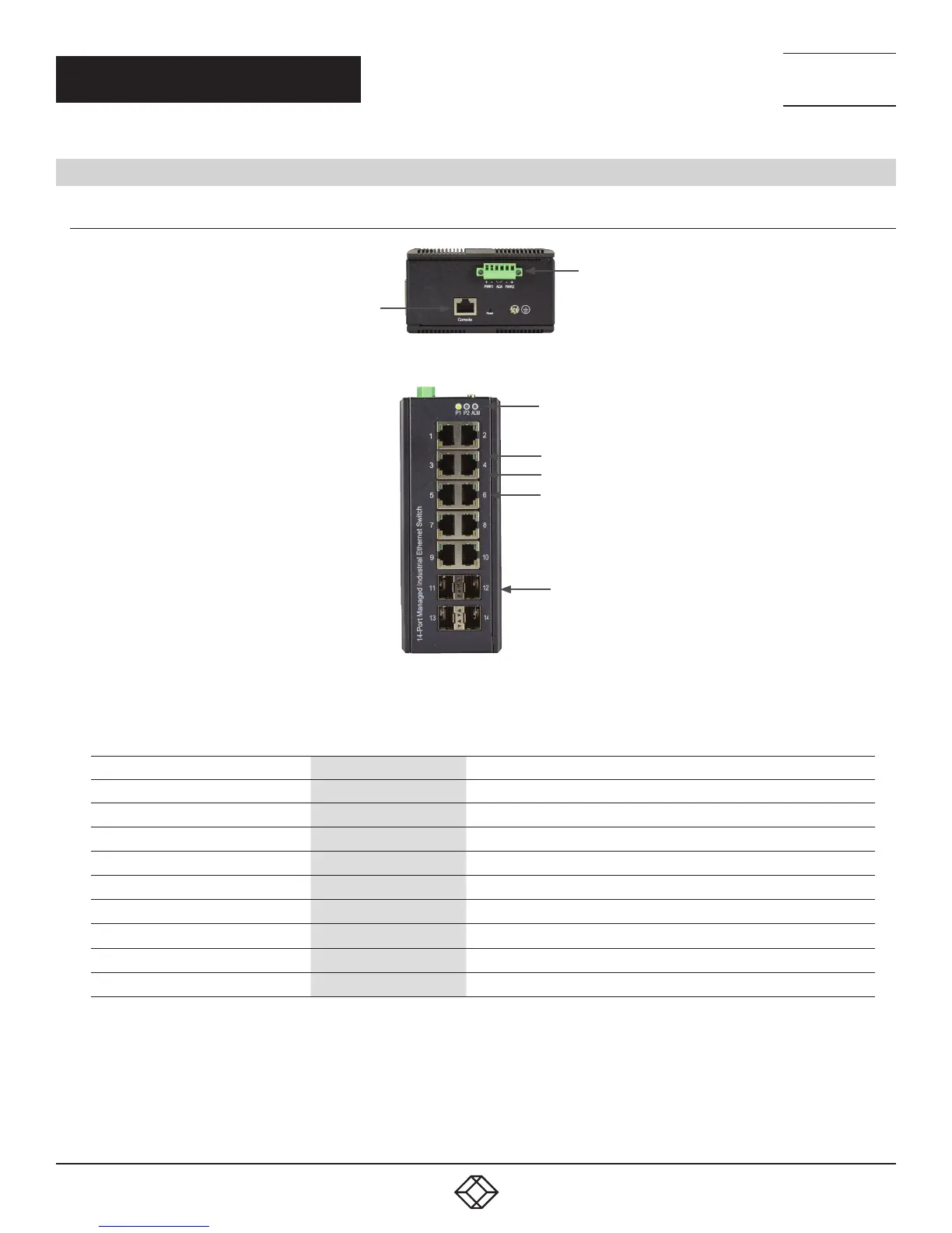
2.5 HARDWARE DESCRIPTION
2.5.1 L I G1014 A
1
2
FIGURE 2-1. LIG1014A TOP PANEL
3, 4, 5
6
7
8
9
FIGURE 2-2. LIG1014A FRONT PANEL
TABLE 2-1. LIG1014A COMPONENTS
NUMBER IN FIGURES 2-1 AND 2-2 COMPONENT DESCRIPTION
1 (1) RJ-45 connector Links to console for management
2 (1) 6-pin terminal block Power 1, Power 2 and Alarm connections
3 (1) P1 LED Lights when power to Power Supply 1 is ON
4 (1) P2 LED Lights when power to Power Supply 2 is ON
5 (1) Alarm LED Lights to indicate an alarm
6 (10) Link/Activity LEDs Lights when there is activity on the respective port
7 (10) Speed LEDs Lights when port is operating at 100 Mbps
8 (10) RJ-45 connectors Connect to devices
9 (4) SFP module cages Connect to fiber optic uplinks