22
1.8 7 7. 87 7. 2 2 6 9 BLACKBOX.COM
NEED HELP?
LEAVE THE TECH TO US
LIVE 24/7
TECHNICAL
SUPPORT
1.8 77.87 7.2269
CHAPTER 3: INSTALLATION
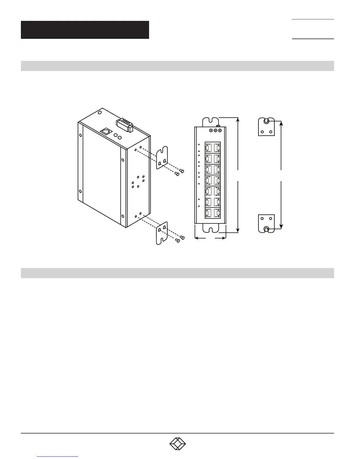
3.2 WALLMOUNTING
Follow these steps to mount the switch on a wall.
1. Screw the wall-mount brackets on with screws in the accessory kit.
–
–
–
–
–
–
–
–
–
–
–
–
–
–
–
–
–
–
–
–
–
–
–
–
–
–
–
–
–
–
–
–
–
–
–
–
–
–
–
–
–
–
–
–
–
–
–
–
–
–
–
–
–
–
–
–
1
1
2
3
4
5
6
5
6
P1
POE
P2
ALM
2
3
4
5
6
7
8
9 10
–
–
–
–
–
–
–
–
–
–
–
–
–
–
–
–
–
–
–
–
–
–
–
–
–
–
–
–
11
12
13
14
–
–
–
–
–
–
–
–
–
–
–
–
–
–
FIGURE 3-3. MOUNTING THE SWITCH ON A WALL
3.3 ALARM RELAY AND GROUND
The alarm relay output contacts are in the middle of the DC terminal block connector as shown in the next figure.
The alarm relay out is “Normal Open,“ and it will be closed when the switch detects any predefined failure such as power failures or
Ethernet link failures.
The relay output has a current carrying capacity of 0.5 A @ 24 VDC.
The switch must be properly grounded for optimum system performance.