23
1.8 7 7. 87 7. 2 2 6 9 BLACKBOX.COM
NEED HELP?
LEAVE THE TECH TO US
LIVE 24/7
TECHNICAL
SUPPORT
1.8 77.87 7.2269
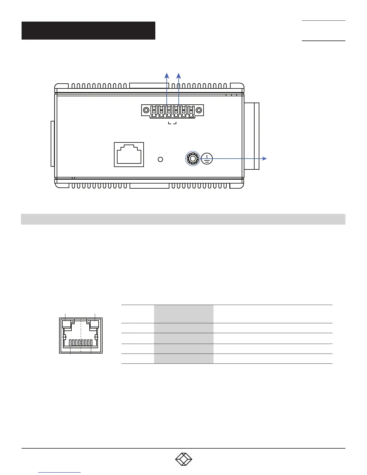
CHAPTER 3: INSTALLATION
PWR1
CONSOLE
RESET
+ – – +
+
ALM PWR2
GROUND CONNECTOR
ALARM SYSTEM
EXTRA POWER SYSTEM
FIGURE 3-4. ALARM RELAY AND GROUND
3.4 CONNECTING THE ETHERNET INTERFACE (RJ-45 ETHERNET)
The switch provides two types of Ethernet interfaces: electrical (RJ-45) and optical (SFP) interfaces.
Connecting the Ethernet interface via RJ45:
To connect the switch to a PC, use straight-through or cross-over Ethernet cables,
To connect the switch to an Ethernet device, use UTP (Unshielded Twisted Pair) or STP (Shielded Twisted Pair) Ethernet cables.
The pin assignment of RJ-45 connector is shown in the following figure and table.
TABLE 3-1. RJ-45 PINOUT
PIN 8
PIN 1
LED A
LED B
PIN ASSIGNMENT
POE ASSIGNMENT
(FOR POE MANAGED SERIES ONLY)
1, 2 T/Rx+, T/Rx- Positive VPort
3, 6 T/Rx+, T/Rx- Negative VPort
4, 5 T/Rx+, T/Rx- X
7, 8 T/R x+, T/Rx- X