39
1.8 7 7. 87 7. 2 2 6 9 BLACKBOX.COM
NEED HELP?
LEAVE THE TECH TO US
LIVE 24/7
TECHNICAL
SUPPORT
1.8 77.87 7.2269
CHAPTER 4: VLAN APPLICATION
4.3 EXAMPLE 3: IEEE 802.1Q TAGGING
The switch is able to construct a layer-2 broadcast domain by identifying VLAN ID specified by IEEE 802.1Q. It forwards a frame
between bridge ports assigned to the same VLAN ID and can set multiple VLANs on each bridge port.
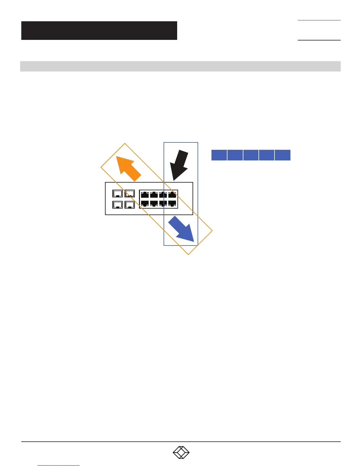
In the following figure, the tagged incoming packets are assigned directly to VLAN 100 and VLAN 200 because of the tag
assignment in the packet. Port 2 is configured as a tagged member of VLAN 100, and Port 7 is configured as an untagged
member of VLAN 200. Hosts in the same VLAN communicate with each other as if they in a LAN. Hosts in different VLANs cannot
communicate with each other directly.
8
7
10
9
5 3
1
6
4 2
TAGGED PACKET:
VID = 100
VID = 200
CRC
DA
SA
DATA
BEFORE
TAG
GROUP B
GROUP A
UNTAGGED MEMBER
OF VLAN 200
TAGGED MEMBER
OF VLAN 100
PORT 7
PORT 2
PORT 1
GROUP A (VLAN 100): PORT 1 AND PORT 2
GROUP B (VLAN 200): PORT 1 AND PORT 7
FIGURE 4-5. IEEE 802.1Q TAGGING EXAMPLE
In this case:
1. The hosts from Group A can communicate with each other.
2. The hosts from Group B can communicate with each other.
3. The hosts of Group A and Group B can’t communicate with each other.
4. Both the Group A and Group B can go to Internet through the switch.