40
1.8 7 7. 87 7. 2 2 6 9 BLACKBOX.COM
NEED HELP?
LEAVE THE TECH TO US
LIVE 24/7
TECHNICAL
SUPPORT
1.8 77.87 7.2269
CHAPTER 4: VLAN APPLICATION
CONFIGURATION
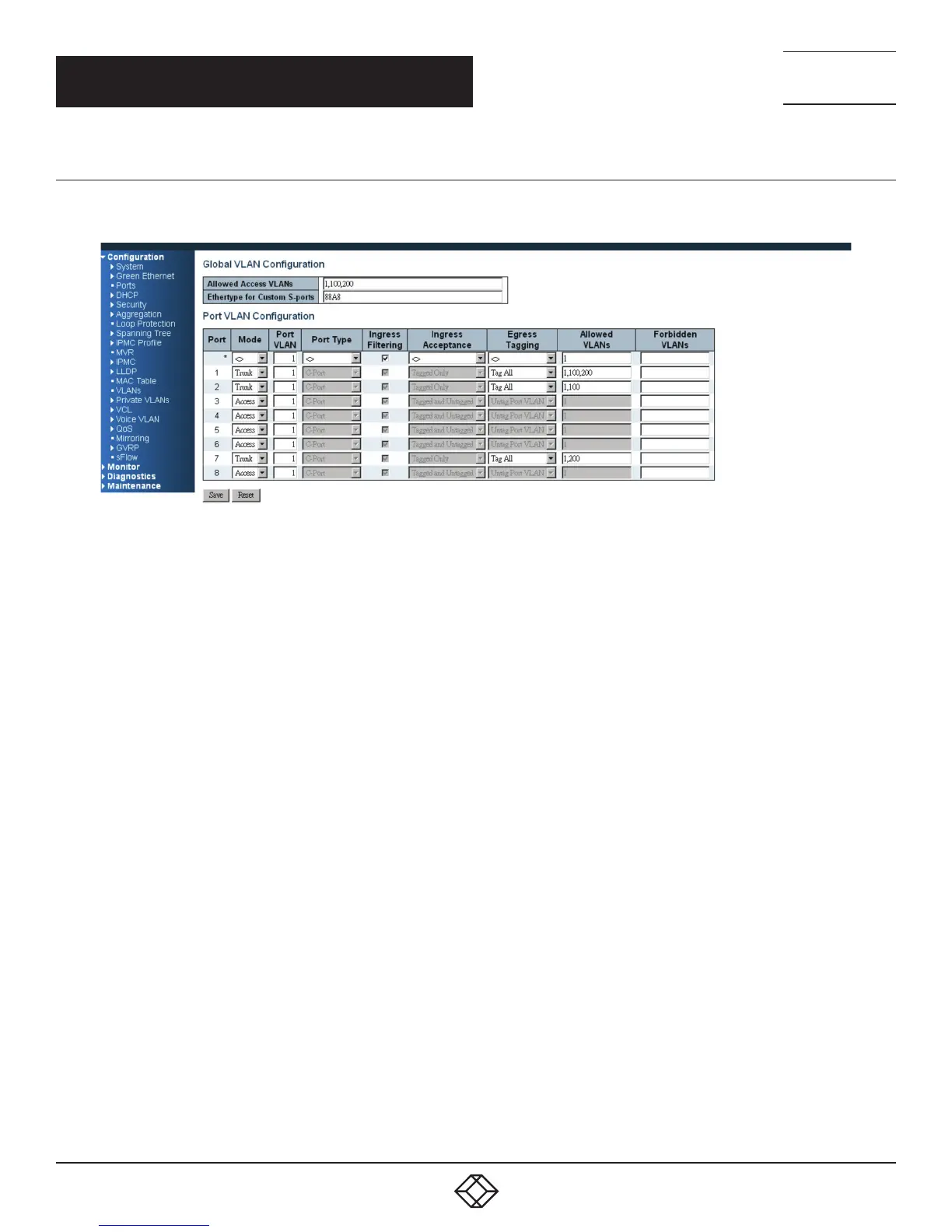
STEP 1: Go to C configuration -> VLANs -> Port VLAN configuration page specify the VLAN membership as follows:
FIGURE 4-6. EXAMPLE 3 CONFIGURATION SCREEN
STEP 2: Transmit unicast packets with VLAN tag 100 from Port 1 to Port 2 and Port 7. The switch should tag it with VID 100.
The packet only has access to Port 2. For Port 2, the outgoing packet leaves as a tagged packet with VID 100.
STEP 3: Transmit unicast packets with VLAN tag 200 from Port 1 to Port 2 and Port 7. The switch should tag it with VID 200.
The packet only has access to Port 7. The outgoing packet on Port 7 is stripped of its tag as an untagged packet.
STEP 4: Transmit unicast packets with VLAN tag 100 from Port 2 to Port 1 and Port 7. The switch should tag it with VID 100.
The packet only has access to Port1. For Port 1, the outgoing packet leaves as a tagged packet with VID 100.
STEP 5: Transmit unicast packets with VLAN tag 200 from Port 7 to Port 1 and Port 2. The switch should tag it with VID 200.
The packet only has access to Port1. The outgoing packet on Port 1 will leave as a tagged packet with VID 200.
STEP 6: Repeat the above steps using broadcast and multicast packets.