EP600 Energy Storage System User Manual
6.4 Connection ground protection(PE)
The PV positive pole and negative pole of the inverter cannot be grounded,
otherwise the inverter will fail.
In EP600 energy storage system, all non-current carrying metal parts (such as
bracket, distribution box, inverter shell, battery pack shell, etc.) should connect
to the ground.
Prerequisite: Prepare the ground cable (2.5mm
2
~ 4mm
2
yellow green outdoor power cable and
Rnb3.5-5s round bare terminal are recommended)
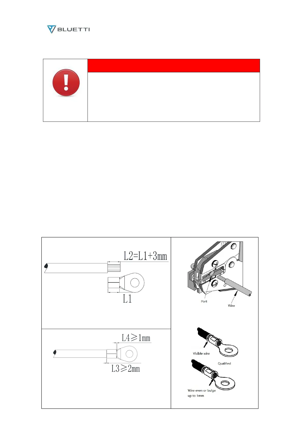
Step 1: Strip the insulation layer of the ground cable with a wire stripper to a proper length (as shown in
Figure. 6-3-1).
Step 2: Thread the stripped insulation core into the conductor crimping area of OT terminal and press it
tightly with crimping pliers (as shown in the figure 6-3-2)。
Step 3: Fix the to terminal with M5 screws at the position shown in figure 6-3-3. The locking torque is
recommended to be 3nm.
Note 1: L3 is the distance between the insulated terminal surface of the cable and the rear section of the
terminal conductor crimping area, and L4 is the length of the conductor of the cable protruding from the
terminal conductor crimping area.
Note 2: The cavity formed after the crimping of the conductor crimping piece of the terminal should
completely cover the cable conductor, and the cable conductor and the terminal should be closely
combined.