EP600 Energy Storage System User Manual
External DC can not exceed 30Vdc/3A
(Reserved for ignition of diesel
generator)
SPDT relay normally closed output
port
SPDT relay normally opened output
port
Signal input/output ground
Signal input, active low (Connected to signal
ground)
Signal output, active low
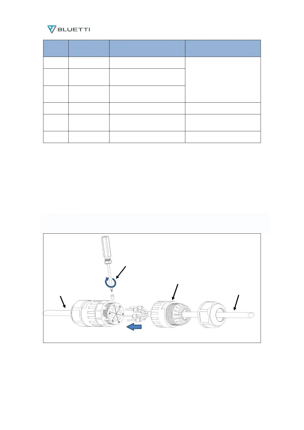
Operation steps.
Step1: Remove the unconnected end of the DRMs connector adapter counterclockwise.
Step2: Thread the extension cable into the connector shell and install the corresponding signal cable into
the connector pins.
Step3: Tighten the screws of the connector with a screwdriver.
Step4: Gently pull the connection cable of 6 pins to determine whether the connection is tight;
Step5:Tighten the connector shell and nut clockwise.
Tighten
the screw
Connector housing
DRMs cables Signal extension cable