56,5
445
137
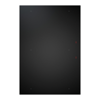
PURU Schablone für Rückwandausschnitt
R12,5
PURUBP-000
132
125
PURU Template for cut-out on rear wall
132
10
20
30
40
0
10
20
30
40
0
10
20
30
40
0
10
20
30
40
0
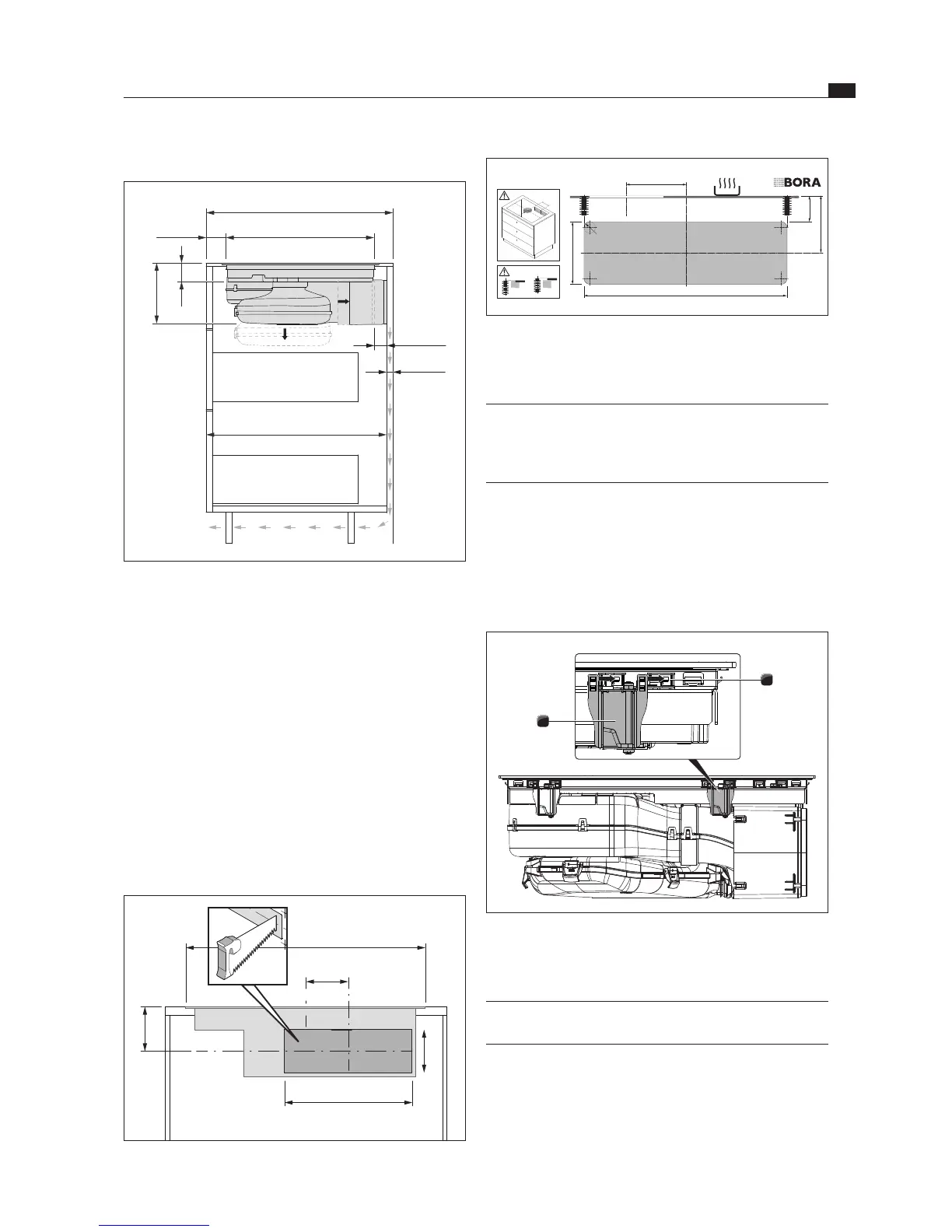
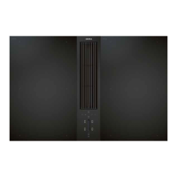
Fig. 6.12 Template for back wall cut-out
Position the template on the back wall of the unit with
the help of the markings and instructions.
INFO Centre of cut-out (horizontal): 125 mm from
the top edge of the cooktop Centre of cut-out
(vertical): Offset 132 mm from the centre of the
cooktop.
Draw the bore hole accordingly with the aid of the
drilling template provided.
Saw out the return flow aperture.
Decrease the height of the skirting boards or create
corresponding openings in the plinth.
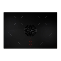
Inserting the cooktop
1
2
Fig. 6.13 Inserting the cooktop
[1] Retaining brackets
[2] Montageklemmen
INFO 2 installation claps must be fitted to each side of
the cooktop.
Slide the 4 installation clamps [2] until they reach
the stop position in the retaining brackets [1] on the
bottom of the cooktop.
Installation dimensions
545–625
68
199
max. 80
min. 25
min. 600
min. 50 495
Fig. 6.10 Installation dimensions for recirculation, depth of
worktop 600 mm
The floor unit must have a continuous back wall so
that the recirculated air is not directed into the front
furniture body compartment.
There must be a cut-out in the back wall.
A minimum clearance of 25 mm between the back
furniture body wall and an adjacent kitchen unit
or room wall must be observed for the return flow
aperture.
Preparing the back wall of the kitchen unit
Adapt the back wall according to the required
installation dimensions.
If applicable, move the back wall.
If necessary extend the height of the back wall so that
the unit is closed to the front.
125
137
445
132
764