Page 22 P/N: 4998122677Cr1 Copyright 2003 Bosch Security Systems DS7240-UK Reference Guide
PART II: SYSTEM INSTALLATION AND SETUP
15.6 DX3010 Address Programming
Each DX3010 module connected to the panel must
have its own address DIP switches set to either
address shown in Table 7.
Output # Data Bus Address
5 to 12 Data Bus Address 150
13 to 20 Data Bus Address 151
Table 7: DX3010 Addresses
Any time the address DIP switches are
changed, you must cycle the power to the
module OFF and then ON for the changes to
take effect.
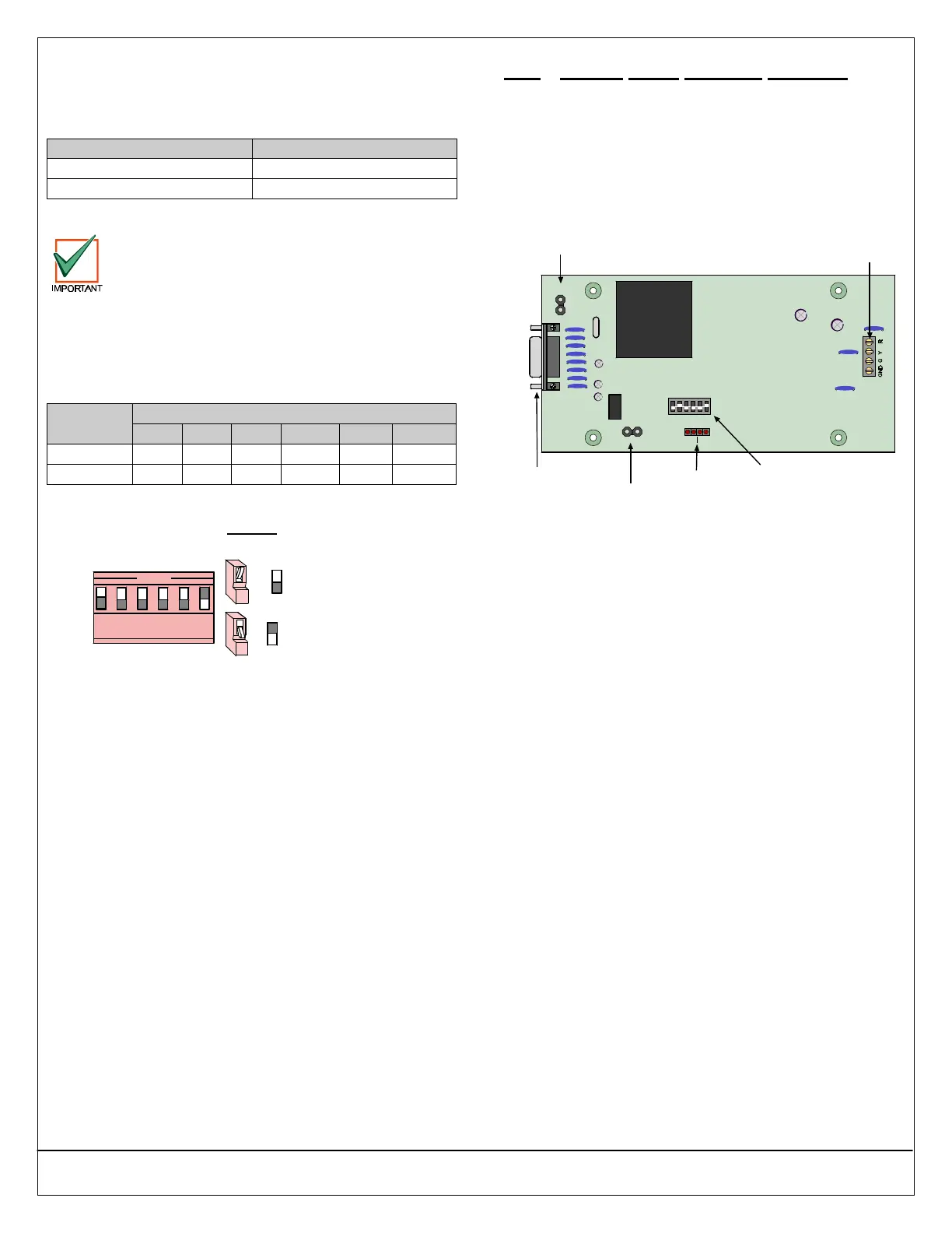
Set the address DIP switches as shown in Table 8.
“DN” indicates that the DIP switch is CLOSED
(Down); “UP” indicates that the DIP switch is OPEN
(Up). See Figure 34 for DX3010 DIP switch
configuration.
DX3013 DIP Switches
Data Bus
Address
1 2 4 8 16 MODE
150 UP UP UP UP UP DN
151 DN UP UP UP UP DN
Table 8: DX3013 Address DIP Switch Settings
Example:
Module Address 150
= Switch OPEN (Up)
=
= Switch CLOSED (Down)=
OPEN
1 2 3 4 5 6
Figure 34: DX3010 DIP Switch Configuration
16.0 RS-232 Serial Interface (DX4010)
16.1 DX4010 Overview
The DX4010 RS-232 Serial Interface Module can be
used to connect a standard serial printer, or other
serial device, to the control panel. It can also be used
for a DSRPS-INT’L remote programming direct
connection. Refer to the DX4010 Installation Guide
(P/N: 49539) for complete installation, addressing and
operating instructions.
DB9 GND
Enable Pins (P1)
Diagnostic LED
Enable Pins (P2)
SER RXTX BUSRXTX
LED ENABLE
DB9 GND
ENABLE
P1
P5
ON
1 2 3 4 5 6
1 2 4
8
16 M
P2
DB9 Connector
Diagnostic LEDs
Address DIP Switches
Data Bus
Figure 35: DX4010 PCB
16.2 DX4010 Installation
The intended installation location for the DX4010 is
in the plastic enclosure that it is shipped in. This is a
low-profile, aesthetically appealing housing that can
be placed on a desktop or similar surface.
Distance from the panel is determined by the total
combined wire length of all devices (including
keypads) connected to the panel’s Data Bus
terminals. The combined total wire length must not
exceed 305 m for #22 AWG (0.8 mm), or 610 m for
#18 AWG (1.2 mm).


 To Next Page