1/05 | F01U002505B
EN | 12FPT-DACT | Operation & Installation Guide |
2.0 Installation
2.2 Connecting the FPT-DACT
2.2.1 Input Point Connections
Remove all power before making or breaking any connections to the FPT-DACT. Failure to do can
cause personal injury and damage to the equipment.
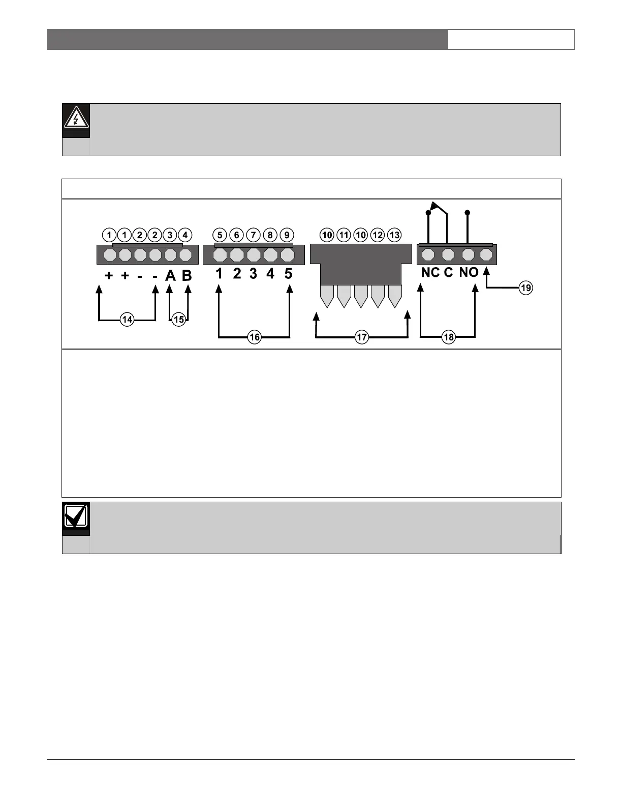
See Figures 7 through 13 (pages 12 through 15) when making connections to the FPT-DACT.
The contact position shows an off-normal condition. Under normal operation, the trouble relay is
energized. Normally, C and NO are connected.
1 - Red (Power +) 11 - Red
2 - Black (Power -) 12 - Green
3 - TX/A 13 - Yellow
4 - RX/B 14 - Power (See Table 1 on page 7 for specifications.)
5 - White/Brown (Input Point 1) 15 - Serial connection pins
6 - White/Red (Input Point 2) 16 - Inputs (See Table 2 on page 7 for specifications.)
7 - White/Orange (Input Point 3) 17 - Keypad terminals
8 - White/Yellow (Input Point 4) 18 - Trouble relay (Connect to input on the FACP for trouble annunciation.)
9 - White/Blue (Input Point 5) 19 - This terminal is not used.
10 - Black
Figure 7: Molex Connector Descriptions