EN | 15FPT-DACT | Operation & Installation Guide |
1/05 | F01U002505B
2.0 Installation
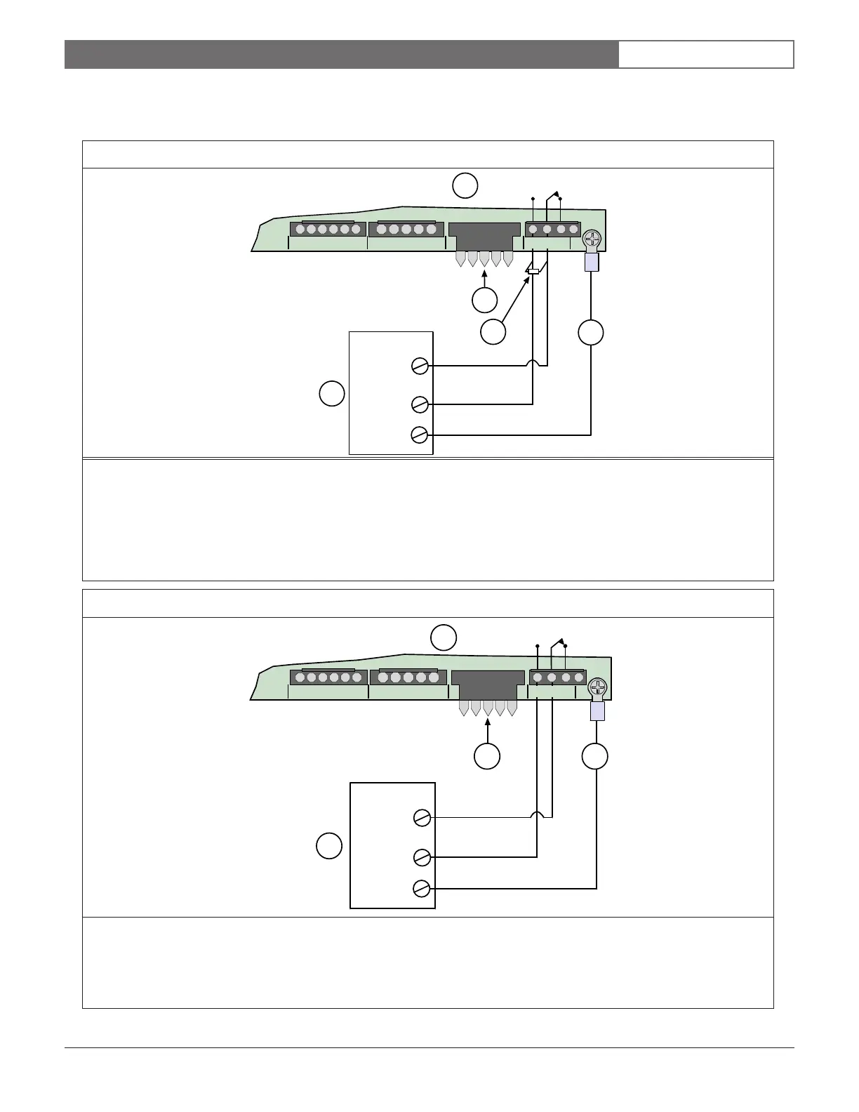
2.2.2 Trouble Relay Connections
Refer to Figure 12 when making connections to the FPT-DACT Trouble Relay terminals.
1
++
-
AB
345
NO
2
-
1
NC C
{
Zone
Input
Earth
Ground
KEYPAD
3
4
2
Figure 13: Typical Trouble Relay Connections (Non-supervised)
1 - FPT-DACT 3 - Earth ground (green)
2 - Keypad terminals 4 - FACP
Note: For the UL installations, non-supervised operation requires installation within 20 ft (6 m) inside the conduit.
Note: The contact position shows an energized condition, normal standby.
Figure 12: Typical Trouble Relay Connections (Supervised)
1 - FPT-DACT
2 - Keypad terminals
3 - EOL resistor (See the FACP Installation Instructions for UL approved EOL resistor specifications.)
4 - Earth ground (green)
5 - FACP
Note: The contact position shows the energized condition (normal standby).
++
-
AB
345
NO
2
-
1
NC C
{
Zone
Input
Earth
Ground
KEYPAD
1
4
5
3
2