1/05 | F01U002505B
EN | 8FPT-DACT | Operation & Installation Guide | 1.0 Overview
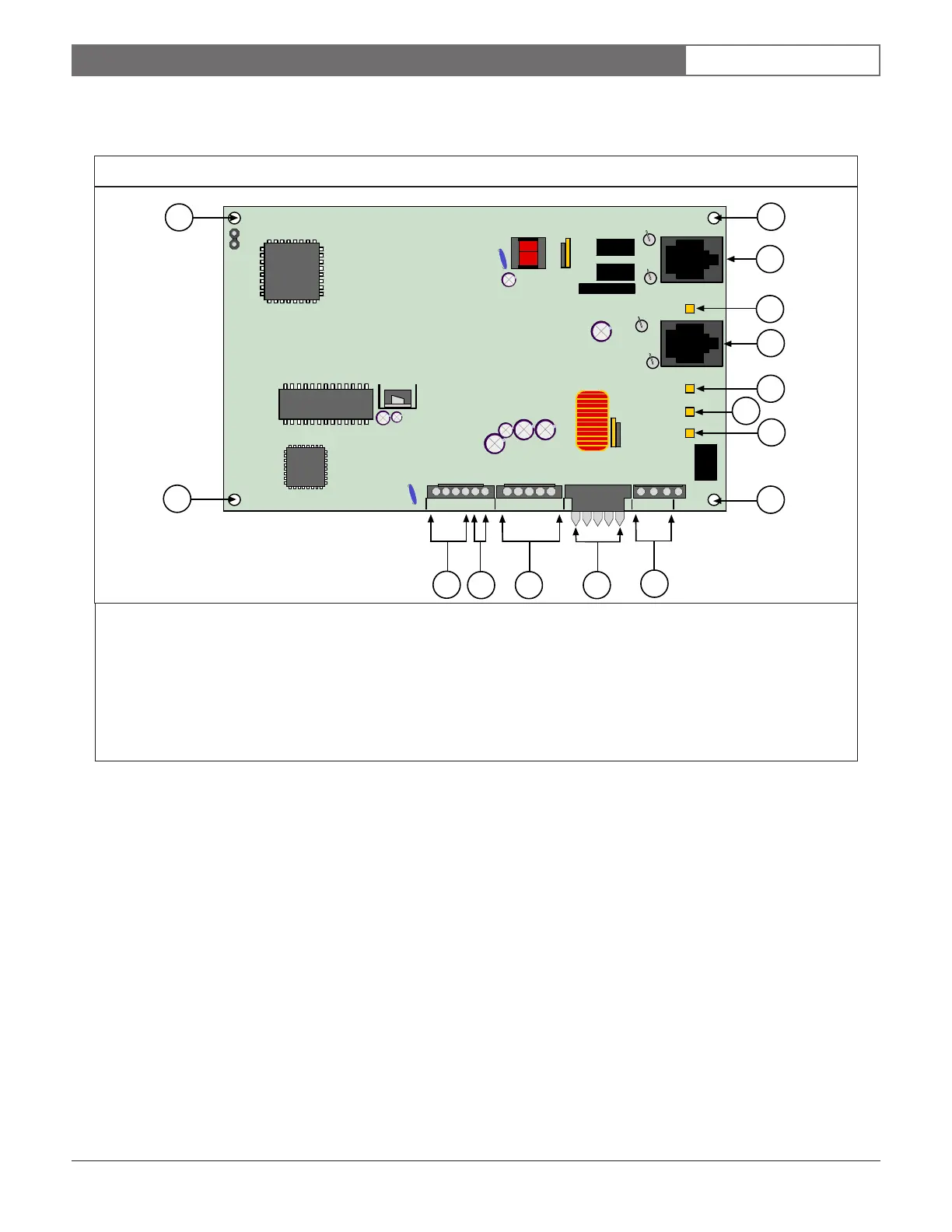
1.2.11 PCB Layout
Figure 1 shows the layout of the FPT-DACT printed circuit board (PCB).
1 - Mounting hole 8 - Mounting hole (Attach the ground wire at this mounting hole.)
2 - Phone line 1 9 - Trouble relay connector pins
3 - Phone line 1 LED 10 - Keypad terminals
4 - Phone line 2 11 - Input molex connector pins
5 - Phone line 2 LED 12 - Serial connector pins
6 - System trouble LED 13 - Power molex connector pins
7 - Heartbeat LED
Figure 1: FPT-DACT PCB Layout
LINE 1
LINE 2
++- -AB
12345
NC C NO
SYS TROUBLE
HEARTBEAT
KEYPAD
4
3
2
5
6
7
1
1
1
9
101112
13
8