EN | 5FPT-DACT | Operation & Installation Guide |
1/05 | F01U002505B
1.0 Overview
Installation Guidelines for UL Systems
Failure to install and program the FPT-DACT
according to the requirements in this section
voids the listing mark of Underwriters
Laboratories, Inc. (UL).
Test according to NFPA 72 Chapter
10.4.1.2 (2002) following any modifications,
repairs, upgrades, or adjustments to the
system.
FPT-DACT UL Requirements
• FPT-DACT is UL Listed for Commercial Digital
Alarm Communicator applications (Type service:
remote station and central station), UL Standard
UL864.
• Install the digital alarm communicator transmitter
(DACT) according to NFPA 72 for Commercial Fire
installations.
• Mount the FPT-DACT indoors and within the
protected area.
• Ground according to Article 250 of the National
Electrical Code NFPA 70.
• Use the supplied screw and clamp terminal to
connect the ground wire provided with the
enclosure. Refer to Figure 5 on page 10.
• Use, enable, and supervise both telephone lines.
• Input points might be unsupervised if the FPT-
DACT is mounted within 20 ft (6 m) of the fire
alarm control panel (FACP) with wiring in conduit.
• If mounting the FPT-DACT more than 20 ft (6 m)
from the FACP, configure all input points for
supervisory operation whether or not conduit is
used.
Use conduit for all installations.
1.0 Overview
1.1 System Overview
The FPT-DACT Fire Communicator is a complete
communicator for use with compatible FACPs. Alarms
and communications to the FPT-DACT are
accomplished using dry contacts or open collector
outputs.
The FPT-DACT also includes:
• 12 VDC or 24 VDC operation
• Multiple data protocols (Modem IIIa
2
, Contact ID,
SIA, and 4/2)
• 100-event history buffer
• Five programmable discrete wire inputs (Class “B”)
• Dual telephone line interface
• Option bus interface for built-in programming using
the FMR-DACT-KEYPAD liquid crystal display
(LCD) Remote Keypad
• Form “C” Relay output for trouble
• LEDs for heartbeat, system trouble, and telephone
line trouble (one per line)
• Real-time clock
1.2 Features and Specifications
1.2.1 Power
Do not share power from the FACP with the
FPT-DACT and other peripheral devices.
Although the FPT-DACT can withstand short power
losses up to 5 min, connect it to an unswitched,
uninterrupted power source.
If the FPT-DACT loses power for more than 5 min, the:
• History buffer might clear and all stored events are
lost.
• Output (report) buffer might clear and all pending
reports are lost.
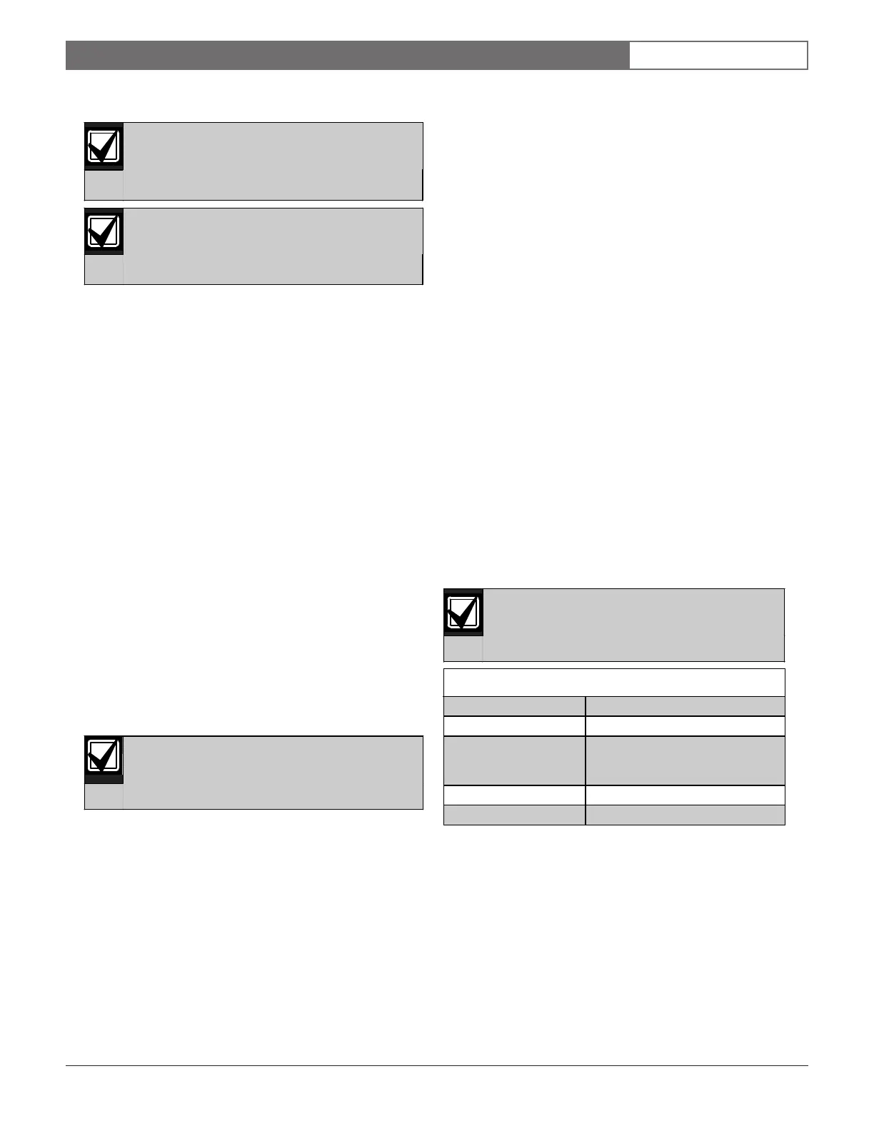
Table 1: Power Specifications
Power Specification FPT-DACT Value
Input voltage range
(use power-limited
source)
10.2 VDC to 28 VDC for filtered
DC; 12 VRMS to 28 VRMS for
unfiltered DC
Standby current 150 mA maximum
Alarm current 190 mA maximum