10 mm² (green/yellow)
6 mm
²
(blue)
PE bar
A
B
A
Overvoltage category I
(4)
6 mm² connect to functional earth of the operator display
6 mm
²
connect to functional earth of the control cabinet PC
6 mm
²
connect to functional earth of the UPS (VAU 01.1)
X1S2
UPS
(VAU 01.1)
0V OUT
24V OUT
X1S1
0V IN
24V IN
(VDP xx.3)
X1S1
+
-
X10
VPB 40.3
+
-
(2)
+24V
0 V
(1)
(4)
(3)
(3)
(5)
16 A
24 V
VPP xx.3
Terminal block UK6-FSI/6
with automatic cut-out TCP 10 A
(PHOENIX CONTACT) is recommended
Terminal block UK6-FSI/6
with automtatic cut-out TCP 4 A
(PHOENIX CONTACT)
Functional earth
Functional earth
Functional earth
VSP xx.3
VSB 40.3
Operator display
Control cabinet PC
VPB 40.4
10 mm² (green/yellow)
A
Terminal block 4 mm
2
B
Terminal block 10 mm
2
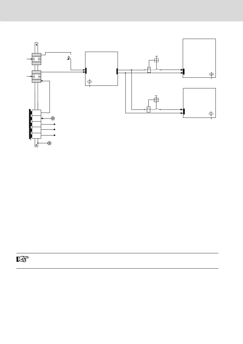
① Easy to remove and visible
② Cable length between the UPS and the
control cabinet PC is max. 2 m at a
cross-section of min. 2.5 mm
2
③ Polarity reversal of the XS1 and X10
plugs can sporadically result in destruc-
tion of the device (fire hazard) if no ad-
ditional external protection is provided.
The reason is a simultaneous grounding
of the 0 V of the device and of the 0 V
(PELV) (1)
④ Cable length between the +24 V power
supply unit and the UPS: 1 m to 7 m,
2.5. mm
2
cross-section, 8 m to 10 m, 4.0
mm
2
cross-section (refer to the docu-
mentation of the UPS VAU01.1)
⑤ Cable length between the +24 V power
supply unit and the operator display is
max. 30 m at a cross-section of min. 1.5
mm
2
. If the cable length exceeds 30 m, a
separate power supply unit is required
Fig. 10-12: Control cabinet PC and operator display connected to a UPS
UPS with USB interface
When connecting a UPS to a USB interface at the control cabinet PC,
information on the existence and the status of the UPS are communicated to the
control cabinet PC.
A UPS with USB interface is absolutely mandatory to reliably back up
remanent control data in the IndraMotion MLC VPB 40.4!
Bosch Rexroth AG
Mounting, demounting and electric installation
IndraControl VPB 40.4
34/87
DOK-MLC***-INDRACTRLV4-IT02-EN-P